ADAM-5510/P31 2-11
Chapter 2
2.6 Wiring and Connections
This section provides basic information on wiring the power supply,
I/O units, communication port connection and programming port
connection.
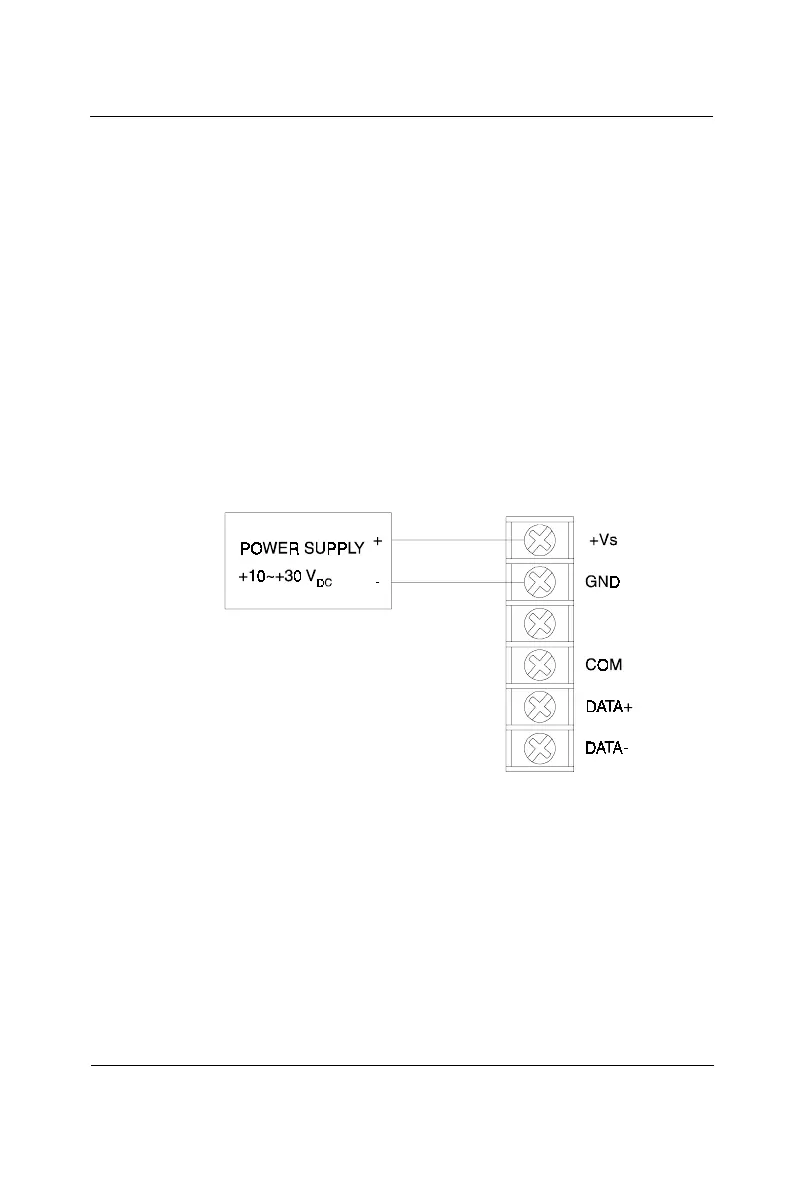
Power supply wiring
Although the ADAM-5510/P31 systems are designed for a standard
industrial unregulated 24 V
DC
power supply, they accept any power
unit that supplies within the range of +10 to +30 V
DC
. The power
supply ripple must be limited to 200 mV peak-to-peak, and the immedi-
ate ripple voltage should be maintained between +10 and +30 V
DC
.
Screw terminals +Vs and GND are for power supply wiring.
Note: The wires used should be sized at least 2 mm
2
.
Figure 2-11: ADAM-5510/P31 power wiring
I/O modules wiring
The system uses a plug-in screw terminal block for the interface
between an I/O module and field devices. The following information
must be considered when connecting electrical devices to I/O mod-
ules.
1. The terminal block accepts wires from 0.5 mm
2
to 2.5 mm
2.
2. Always use a continuous length of wire. Do not combine wires to
make them longer.
 Loading...