Home
Advantech
Motherboard
AIMB-784
Advantech AIMB-784 User Manual
5
of 1
of 1 rating
114 pages
Give review
Manual
Specs
To Next Page
To Next Page
To Previous Page
To Previous Page
Loading...
AIMB-784 User
Manual
48
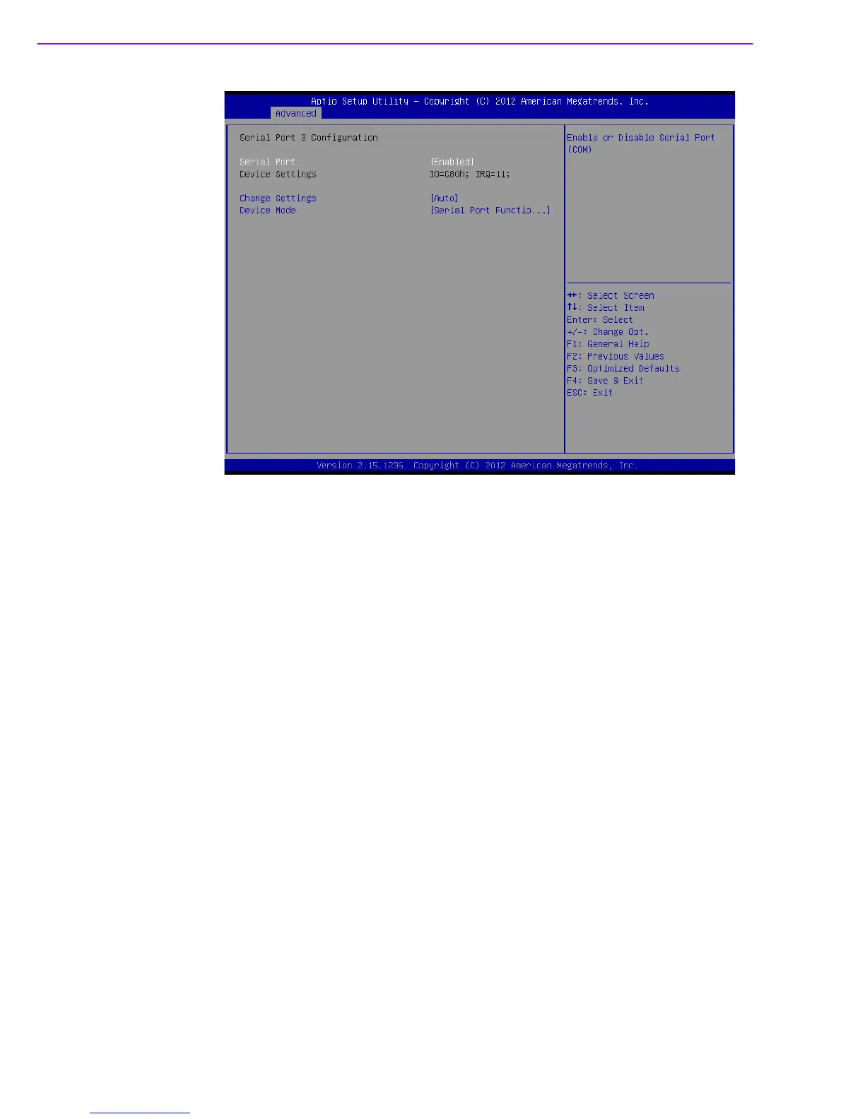
Figure 3.21 Serial Port 3 Configuration
Serial Port 3 Configuration
–
Serial Port
T
o "Enable or Disable" Serial Port 3.
–
Change Settings
T
o select an optimal setting for serial port 3.
–
Device Mode
Can be selected to Serial Po
rt Function Mode (RS-232), RS-485 Ha
lf Duplex,
or RS-422 Full Duplex.
57
59
Table of Contents
Default Chapter
7
Table of Contents
7
Chapter 1 Hardware Configuration
11
Introduction
12
Features
12
Specifications
13
System
13
Memory
13
Input/Output
13
Graphics
13
Ethernet LAN
13
Industrial Features
14
Mechanical and Environmental Specifications
14
Jumpers and Connectors
14
Board Layout: Jumper and Connector Locations
16
AIMB-784 Block Diagram
17
Safety Precautions
18
Jumper Settings
18
How to Set Jumpers
18
CMOS Clear & ME Clear (JCMOS1 & JME1)
19
Watchdog Timer Output (JWDT1)
19
System Memory
20
Memory Installation Procedures
20
Cache Memory
20
Table 1.5: ATX/AT Mode Selector (PSON1)
20
Processor Installation
21
PCI Bus Routing Table
21
Chapter 2 Connecting Peripherals
23
Introduction
24
Parallel Port (LPT1)
24
USB Ports
25
Usb1112 & Usb1314)
25
USB Power Switch
26
VGA Connector and DVI-D Connector (DVI1/DVI2 + VGA1)
26
Serial Ports (COM1, COM2, COM3, COM4, COM5 & COM6)
27
PS/2 Keyboard and Mouse Connector (KBMS1)
27
External Keyboard & Mouse (KBMS2)
28
CPU Fan Connector (CPUFAN1)
28
System FAN Connector (SYSFAN1 and SYSFAN2)
29
Front Panel Connectors (JFP1, JFP2 & JFP3)
29
Power LED and Keyboard Lock (JFP3)
30
External Speaker (JFP2 Pins 1, 4, 7 & 10)
30
HDD LED Connector (JFP2 Pins 2 & 5)
30
SNMP Sm_Bus Connector (JFP2 Pins 8 & 11)
30
ATX Soft Power Switch (JFP1 Pins 3 & 6)
30
Reset Connector (JFP1 Pins 9 & 12)
30
Line Out, MIC in Connector (AUDIO1_AUDIO2)
31
8-Pin Alarm Board Connector (VOLT1)
31
Case Open Connector (JCASE1)
32
Front Panel LAN Indicator Connector (LANLED1)
32
Serial ATA Interface (SATA1, SATA2, SATA3, SATA4, SATA5 & SATA6)
33
PCI Slots (PCI 1 ~ PCI 4)
33
Pcie X16 Expansion Slot (PCIEX16_1)
34
Pciex4_1
34
Pciex1_1
35
Auxiliary 4-Pin Power Connector (ATX12V1)
35
SPI Flash Connector (SPI_CN1)
36
Low Pin Count Connector (LPC1)
36
BIOS Operation
39
Chapter 3 BIOS Operation
39
Introduction
40
Entering BIOS Setup
41
Main Menu
41
Advanced BIOS Features Setup
42
Figure 3.4 PCI Subsystem Settings
43
Figure 3.5 PCI Express Settings
44
Figure 3.6 ACPI Settings
45
Figure 3.7 TPM Settings
46
Figure 3.8 S5 RTC Wake Settings
47
Figure 3.9 CPU Configuration
48
Figure 3.10SATA Configuration
49
Figure 3.11PCH-FW Configuration
50
Figure 3.12Amtconfiguration
51
Figure 3.13USB Configuration
52
Figure 3.14SMART Settings
53
Figure 3.15Super IO Configuration
54
Figure 3.17Serial Port 2 Configuration
55
Figure 3.19PC Health Status
56
Figure 3.20Super IO Configuration
57
Figure 3.21Serial Port 3 Configuration
58
Figure 3.22Serial Port 4 Configuration
59
Figure 3.24Serial Port 6 Configuration
60
Chipset
61
Figure 3.27System Agent (SA) Configuration
66
Boot
69
Security
71
Save & Exit
72
Chapter 4 Chipset Software Installation Utility
73
Before You Begin
74
Introduction
74
Windows 8 / Windows 7 Driver Setup
75
Chapter 5 Integrated Graphic Device Setup
77
Introduction
78
Windows 8/Windows 7 Driver Setup
78
Chapter 6 LAN Configuration
79
Introduction
80
Features
80
Installation
80
Win 8/Win 7 Driver Setup (LAN)
81
Chapter 7 Intel ME
83
Introduction
84
Installation
84
Chapter 8 Intel USB 3.0
85
Introduction
86
Installation
86
Chapter 9 SATA RAID Setup
87
Introduction
88
SATA RAID Driver and Utility Setup
88
Appendix A Programming the Watchdog Timer
89
Watchdog Timer Overview
90
Programming the Watchdog Timer
90
Example Programs
92
Table A.1: Watchdog Timer Registers
92
Appendix B I/O Pin Assignments
97
Parallel Port (LPT1)
98
USB2.0 Type a Port (USB3)
98
USB3.0 Header (USB1314)
99
USB2.0 Header (USB56, USB78, USB1112)
99
VGA Connector (VGA1)
100
DVI Interface
100
RS-232 and COM 3 Interface
101
B.7 RS-232 and COM 3 Interface
101
External Keyboard Connector (KBMS2)
102
PS/2 Keyboard and Mouse Connector (KBMS1)
102
Infrared (IR) Connector (JIR1) and JWDT1 and HW Monitor Alarm (JOBS1)
103
System Fan Power Connector (SYSFAN1/SYSFAN2)
103
Power LED and Keyboard Lock (JFP3)
103
Table B.11:JIR1+JWDT1+JOBS1
103
External Speaker Connector (JFP2)
104
Reset Connector (JFP1)
104
HDD LED Connector (JFP2)
104
ATX Soft Power Switch (JFP1)
105
SNMP SM_BUS Bus Connector (JFP2)
105
USB/LAN Ports (LAN1_USB910 and LAN2_USB12)
105
Line Out, MIC in Connector (AUDIO)
106
Table B.20:USB3.0 Port
106
Front Panel Audio Connector (FPAUD1)
107
8-Pin Alarm Board Connector (VOLT1)
107
Case Open Connector (JCASE1)
108
Front Panel LAN LED Connector (LAN_LED1)
108
SPI_CN1: SPI Flash Card Pin Connector
108
Fixed I/O Ranges Decoded by Intel PCH
109
System I/O Ports
111
DMA Channel Assignments
111
B.26 System I/O Ports
111
Interrupt Assignments
112
1St MB Memory Map
112
B.28 Interrupt Assignments
112
5
Based on 1 rating
Ask a question
Give review
Questions and Answers:
Need help?
Do you have a question about the Advantech AIMB-784 and is the answer not in the manual?
Ask a question
Advantech AIMB-784 Specifications
General
Brand
Advantech
Model
AIMB-784
Category
Motherboard
Language
English
Related product manuals
Advantech AIMB-780
108 pages
Advantech AIMB-785G2-00A2
116 pages
Advantech AIMB-742
124 pages
Advantech AIMB-275
142 pages
Advantech AIMB-581
112 pages
Advantech AIMB-240 Series
99 pages
Advantech ASMB-585
122 pages
Advantech ASMB-785
128 pages
Advantech PCA-6751 Series
111 pages
Advantech SIMB-M21
84 pages
Advantech PCA-6781
68 pages
Advantech PCE-5126
96 pages