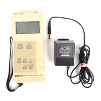
108210 Optical Power Meter
(1) I-V converter
The I-V converter converts the electric current
passing through the sensor into voltage. The
range is divided into eight ranges (20 nW to 200
mW). The feedback resistor is selected for each
range with the R I to R4 signals. Table 3-2 shows
the relationship between the ranges and the R I to
R4 signals. The sensor level is calibrated with the
potentiometer LEVEL A DJ in the sensor.
(2) A/D converter
The A/D converter uses a one-chip A/D conver-
ter with a 2-V full scale and 4 1/2 digits. After
A/D conversion, STRB is output. The CPU
detects this signal and reads the converted data
from the A/D converter.
(3) CPU
The CPU includes ROMs and RAMs. It performs
the following: (I) Range switching for the 1-V
converter, (2) data reading from the A/D conver-
ter, (3) wavelength sensitivity compensation, (4)
display data output to the LCD driver; and (5)
panel key detection. The ROM in the CPU con-
tains wavelength sensitivity correction data (rep-
resentative values). The data set immediately
before power off is backed up with the RAM in
the CPU.
When power is first turned on, the CPU reads sensor
identification codes (SEI to SE3), and determines
which sensor is connected. (See Table 3-2.)
(4) LCD driver
The LCD driver receives data that is serially trans-
ferred from the CPU, and operates the LCDs.
18

 Loading...