VISLINK
Newswift 90-180 Motorised Antenna 15
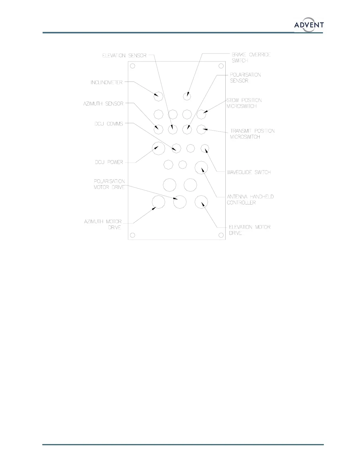
4.3 FRONT AND REAR PANEL
The above diagram shows the front panel layout of the DCU4000.
The AZIMUTH, ELEVATION and POLARISATION MOTOR DRIVE cables go to the stepper
motor, motor rotation detector and brake, if fitted, of the respective drive axis.
The INCLINOMETER cable goes to the RF elevation inclinometer fitted within the elevation
pivot axis cover. This is used to measure the true RF angle of the antenna system, and takes
into account any elevation offset caused by the antenna mount not being horizontal.
The W/G SWITCH cable drives and monitors the waveguide TX polarisation switch fitted
beside the feed horn. (If option fitted.)
The AZIMUTH, ELEVATION and POLARISATION SENSOR cables connect to the Hall
Effect magnetic position sensors for the three axis.
The TRANSMIT and STOW POSITION MICROSWITCH cables connect the two safety inhibit
micro-switches fitted to the elevation axis.
The DCU POWER and DCU COMMS cable run from the antenna to the controlling
ACU4XXX. These cables provide the power for the DCU electronics and motors, and the
serial communications with the ACU4XXX. The connections to the safety micro-switches are
also within the COMMS cable.
The ANTENNA HANDHELD CONTROLLER cable connects to a hand held controller that
enables direct control of each motor axis drive. (If option fitted.)
The manual brake override switch is used to release the brakes on the azimuth or elevation
axis. This allows the antenna to be moved manually.
Any unused cable glands should have a blanking grommet fitted.
 Loading...