VISLINK
Newswift 90-180 Motorised Antenna 17
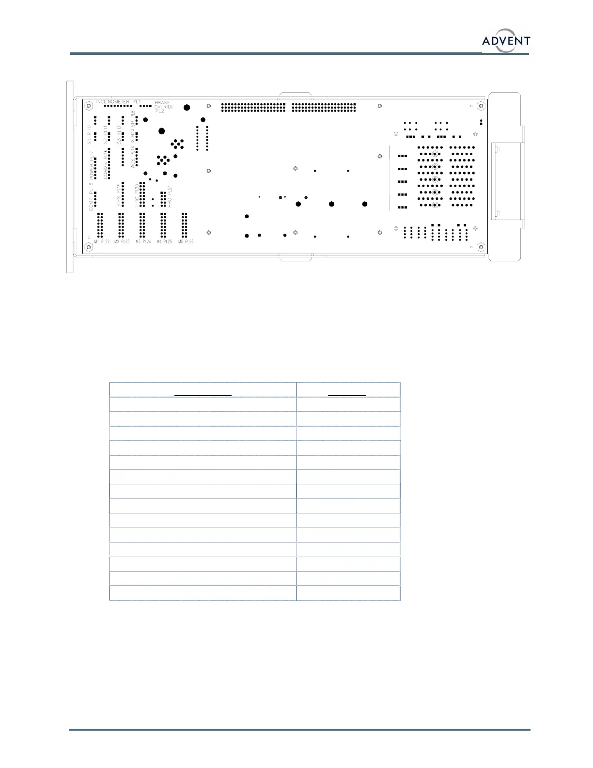
4.6 INTERNAL LAYOUT
4.7 DCU INTERNAL ACCESS
To gain access to the DCU, release the two bolts holding the DCU mounting bracket to the
antenna base plate. Remove the 4 fixings nuts that retain the front panel to the DCU case.
Slide the outer case from the DCU internal chassis.
When re-assembling the DCU, reverse the above sequence, insuring that the sealing gasket
fitted to the DCU front panel internal surface is correctly seated.
4.8 CABLE CONNECTIONS
UCable Name UPlug NoU.
AZIMUTH DRIVE PL22
ELEVATION DRIVE PL23
POLARISATION DRIVE PL24
INCLINOMETER PL1
W/G SWITCH PL14
POWER PL17
COMMS PL16
AZIMUTH SENSOR PL10
ELEVATION SENSOR PL11
POLARISATION SENSOR PL12
STOW POSITION MICROSWITCH PL8
TX POSITION MICROSWITCH PL13
HANDHELD CONTROLLER PL20 & PL21
4.9 SURFACE MOUNT REPLACEABLE FUSES
The DCU electronics boards have two surface mount fuse holders mounted on the internal
PCB’s. These are indicated by F5 and F8. (Bottom board). F5 protects the 12V DC supply
into the whole DCU electronics unit. F8 protects the motor power supply to the DCU.
 Loading...