User Manual 1-3kVA Rev. 9
- Page 17 of Total 30 -
3. Operation
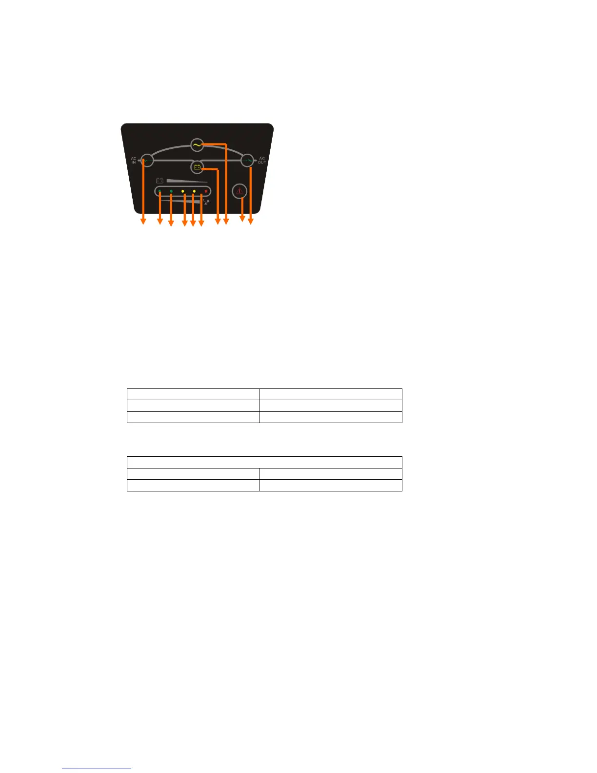
` LED
1 6 7 8 9 10 2 3 4 5
1. Line LED (green): This indicates the AC power is applied to the UPS input. If the LED blinks, it
means the AC power source is out of tolerance.
2. Battery LED (yellow): This indicates the UPS is in Battery Mode.
3. Bypass LED (yellow): This indicates the UPS is in Bypass Mode.
4. Fault LED (red): This indicates the UPS is in fault condition because of UPS shutdown or
over-temperature
5. Inverter LED (green): This indicates the inverter is working normally.
6-10. Load & Battery Capacity LEDs:
(a) No. 6 to 7 LED is green color, No. 8 to 9 is yellow and No.10 (used as warning LED for
overload or battery low) is red.
(b) These LEDs show the load (%) of the UPS if the AC input is available (in Normal Mode).
LEDs light up to indicate the following information.
No. 6 LED: 0-25 % No. 6 - 9 LEDs: 76-100 %
No. 6 - 7 LEDs: 26-50 % No. 6 - 10 LEDs: Overload
No. 6 - 8 LEDs: 51-75 %
(c) In the Battery Mode, the LEDs indicate the capacity (%) of the batteries. LEDs light up
to indicate the following information.
No. 10 LED: 0-25 % (battery low level)
No. 9 - 10 LEDs: 26-50 % No. 7 - 10 LEDs: 76-95 %
No. 8 - 10 LEDs: 51-75 % No. 6 - 10 LEDs: 96-100 %