Switch-mode power supply AC2000 N1 / DC2000 N1 / AC3000 N1 / DC3000 N1 - Operating instructions
80001533 EFE en Page 37 of 41
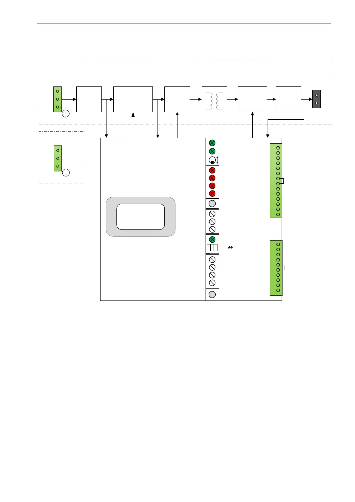
6.6 Block diagram
Synchronous
rectifier
FullbridgePFCbooster
(step‐up
converter)
Mains
filter
Output
filter
L
N
PE
‐X1
L+
L‐
‐X2
Powerstage
AC
Electricalisolation
Monitoring&control
Primary Secondary
L+
L‐
PE
‐X1
DC
Ext.setpointvoltage
0..4V
1
2
3
4
5
6
7
8
9
10
11
12
13
14
Ext.setpointground
+
‐
+
‐
Ext.setpoint+7,5Vref.
+
‐
+
‐
Notconnected
CollectivesignalfaultNC
CollectivesignalfaultCO
CollectivesignalfaultNO
Ext.Setpoint
current0..4V
Externalon
Externalvoltagesensing
‐X11
1
2
3
4
5
6
7
8
9
10
Voltagesetpoint
switching1
+
‐
Voltagesetpoint
switching2
+
‐
Actualvalueoutput0‐10V
(whenshorted)
Actualvaluevoltage
Actualvaluecurrent
‐X12
LEDH1
LEDH2
SwitchS3
LEDH4
LEDH5
LEDH6
LEDH7
ButtonS8
PotiR9
PotiR10
PotiR11
LEDH12
SwitchS13
PotiR14
PotiR15
PotiR16
PotiR17
ButtonS18
Supply
Operation
On
Off
U
Out
Dev.
Temp.>
U
Out
>
U
Out
<
Reset
I
Out
≤
U
Out
≥
U
Out
≤
Ext.U
Out
Set
Int.
Ext.
TrickleCharge
Charge
EPS/Test
Ext.Adjust.
LEDTest
P1
LCdisplay
Voltage/current
Actualvalueground
Actualvalueground
Illustration 9: Block diagram. The European colour scheme is shown for the LEDs.