Switch-mode power supply AC2000 N1 / DC2000 N1 / AC3000 N1 / DC3000 N1 - Operating instructions
80001533 EFE en Page 40 of 41
7.6 Troubleshooting, fault diagnosis and repair
7.6.1 No output voltage present
Mains voltage present at X1 and within tolerance?
Upstream fuses checked?
For devices in the DC series: correct polarity?
For parallel operation: Are any decoupling diodes in output X2
correctly polarized?
Are jumper X11:7 and X11:8 present or is the contact for External
On/Off closed? Is switch S3 (On/Off) switched on?
Output X2 polarity reversed?
Has the monitoring U
Out
≥ responded (LED H6 U
Out
> lights up)?
Press reset S8 (section 6.2.8) and check the overvoltage
monitoring setting with potentiometer R10 U
Out
≥ (section
6.2.5). Make sure which setpoint value U
Out
is selected (section
6.3.4).
Has the overtemperature monitor responded (LED H5 Temp. >
illuminated)?
Press reset S8 (section 6.2.8)!
7.6.2 Deviation of the output voltage
Is the device operating in the current limit due to overload?
Reduce the load!
Is the wrong internal setpoint U
Out
selected?
Is the setting of the selected potentiometer U
Out
(R14-R17)
incorrect?
Adjust the output voltage (section 6.2.5)!
Are the bridges X12:1-2 and X12:3-4 available?
Build bridges!
If an external sensor line is used, is the sensor line open?
If external setpoint specification, setpoint correct?
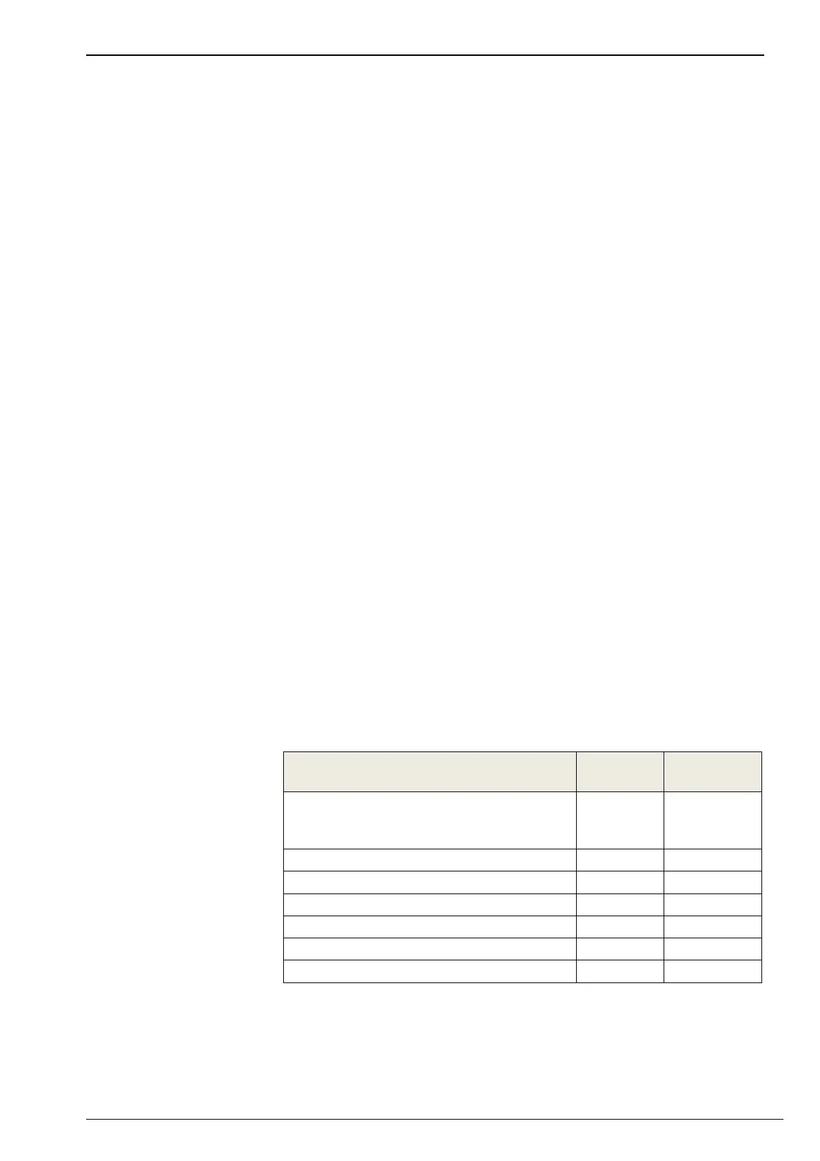
7. 7 Spare parts list
Naming
AEG part
no.
Installed
quantity
Accessory set, consisting of the
following individual parts, among
others:
20010565 1
3-pin mains plug X1 40013216 1
14-pin remote signalling connector X11 40013189 1
10-pin remote signalling connector X12 40013188 1
Shield clamp 40000385 1
Connection cover X2 40000962 1
M3x10 screw for connection cover 40009742 2
Spare parts are not included in the scope of delivery.