Switch-mode power supply AC2000 N1 / DC2000 N1 / AC3000 N1 / DC3000 N1 - Operating instructions
80001533 EFE en Page 27 of 41
The input must be fused outside the appliance
(section 4).
5.5.2 DC output X2 (U )
Out
Please observe the torque specification in the technical data
(section 4).
Excessive torque can lead to damage.
5.5.3 Remote signal connections X11 and X12
The signalling and external setpoint specifications/switchover take
place via connectors X11 and X12 (pin assignment section 3.1;
functional description section 6).
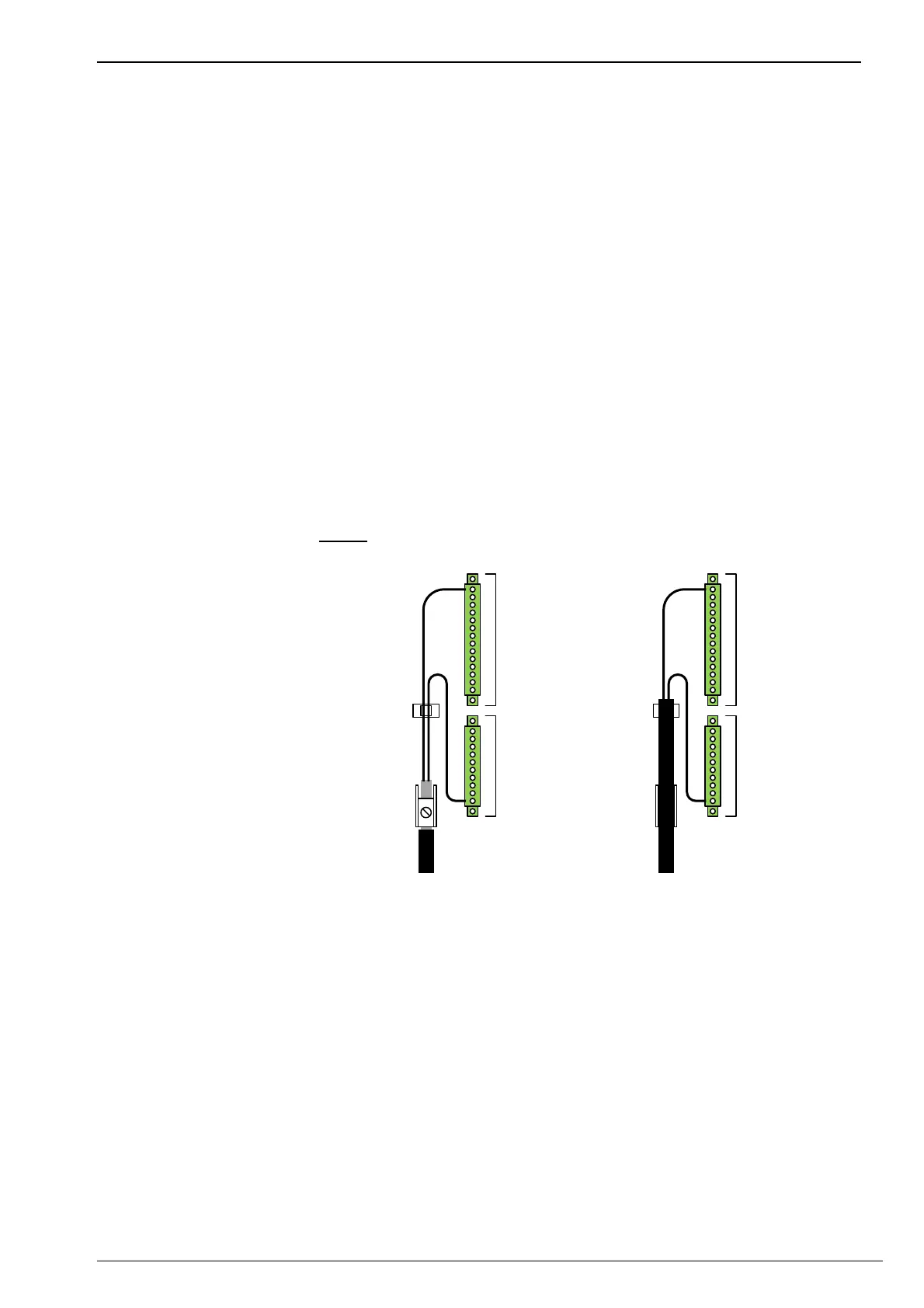
When wiring with a shielded control cable, the enclosed shield terminal
to the left of X12 can be used if required.
Alternatively, the shield clamp can be removed to screw on an M3
cable lug or a screw base for cable ties .
Note: When using the shield clamp, remove the M3 screw underneath
if necessary.
X11
X12
Variant:Shieldedcable
X11
X12
Variant:Controlcable
Shie ld clamp
Cabletie
Cabletie
Cabletie
(throughcabletie
socketM3)
Illustration 6: Example of routing the remote signal cables X11 and X12.
Cables are not included in the scope of delivery.
5.5.4 Cooling and supply air
The switched-mode power supply works with convection cooling. The
air flows from bottom to top through the device and over the heat sink
at the rear. The supply and exhaust air must not be obstructed and
must be routed in such a way that it does not lead to heat build-up. The
supply air temperature must not exceed the specification in the
technical data (section 4.2).