INSTALLATION
2-7
mA OUT
RS-485
COMM.
+
-
+
-
ANALOG IN
SENSOR COMMON
OUTDOOR SENSOR IN
REMOTE INTL'K IN
B.M.S. (PWM) IN
SHIELD
+
-
+
-
(AIR) AUX SENSOR IN
NOT USED
EXHAUST SWITCH IN
DELAYED INTL'K IN
FAULT RELAY
120 VAC, 5A, RES
AUX RELAY
120 VAC, 5A, RES
G
RELAY CONTACTS:
120 VAC, 30 VDC
5 AMPS RESISTIVE
DANGER
120 VAC USED
IN THIS BOX
NOT USED
NOT USED
NC
COM
NO
NC
COM
NO
NOT USED
0 – 10V
AGND
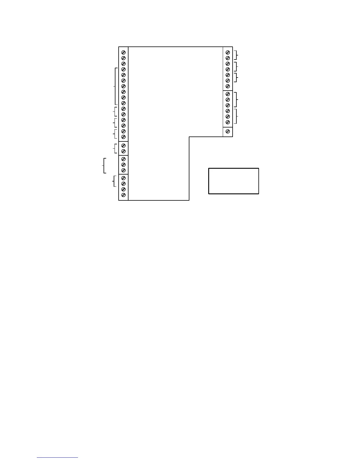
Figure 2-10. I/O Box Terminal Strip
2.9.3 Boiler Management System Mode
NOTE
BMS Model 168 can utilize either pulse
width modulation (PWM) or RS485
Modbus signaling to the Boiler. BMS II
Model 5R5-384 can utilize only RS485
signaling to the Boiler.
When using an AERCO Boiler Management
System (BMS), the field wiring is connected
between the BMS Panel and each Boiler’s I/O
Box terminal strip (Figure 2-10). Twisted
shielded pair wire from 18 to 22 AWG must be
utilized for the connections. The BMS Mode can
utilize either pulse width modulation (PWM)
signaling, or RS485 Modbus signaling. For PWM
signaling, connections are made from the
AERCO Boiler Management System to the
B.M.S. (PWM) IN terminals on the I/O Box
terminal strip. For RS485 Modus signaling,
connections are made from the BMS to the
RS485 COMM terminals on the I/O Box terminal
strip. Polarity must be maintained and the shield
must be connected only at the AERCO BMS.
The boiler end of the shield must be left floating.
For additional instructions, refer to Chapter 5,
paragraph 5.6 in this manual. Also, refer to
GF-108M (BMS Model 168) and GF-124 (BMS II
Model 5R5-384), BMS -Operations Guides.
2.9.4 Remote Setpoint and Direct Drive
Modes
The boiler can accept several types of signal
formats from an Energy Management System
(EMS), Building Automation System (BAS) or
other source, to control either the setpoint
(Remote Setpoint Mode) or valve position
(Direct Drive Mode) of the Boiler. These formats
are:
• 4 to 20 mA/1 to 5 VDC
• 0 to 20 mA/0 to 5 VDC
• PWM – (Pulse Width Modulated signal. See
para. 2.10.4)
• Network (RS485 Modbus. See para. 2.10.7)
While it is possible to control a boiler or boilers
using one of the previously described modes of
operation, it may not be the method best suited
for the application. Prior to selecting one of
these modes of operation, it is recommended
that you consult with your local AERCO
representative or the factory for the mode of
operation that will work best with your
application. For more information on wiring the
4 to 20 mA / 1 to 5VDC or the 0 to 20 mA / 0 to 5
VDC, see paragraph 2.9.3.