INITIAL START-UP
5. Attach one end of the plastic tubing to the
barbed fitting and the other end to the 16
inch W.C. manometer.
MANUAL
SHUT-OFF
VALVE
TO AIR/
FUEL
VALVE
GAS
INLET
1/8" NPT PLUG
(INSTALL
MANOMETER
HERE)
LOW GAS
PRESSURE
SWITCH
HIGH GAS
PRESSURE
SWITCH
SSOV
Figure 4-1.
1/8" NPT Plug Location On Leak
Detection Ball Valve
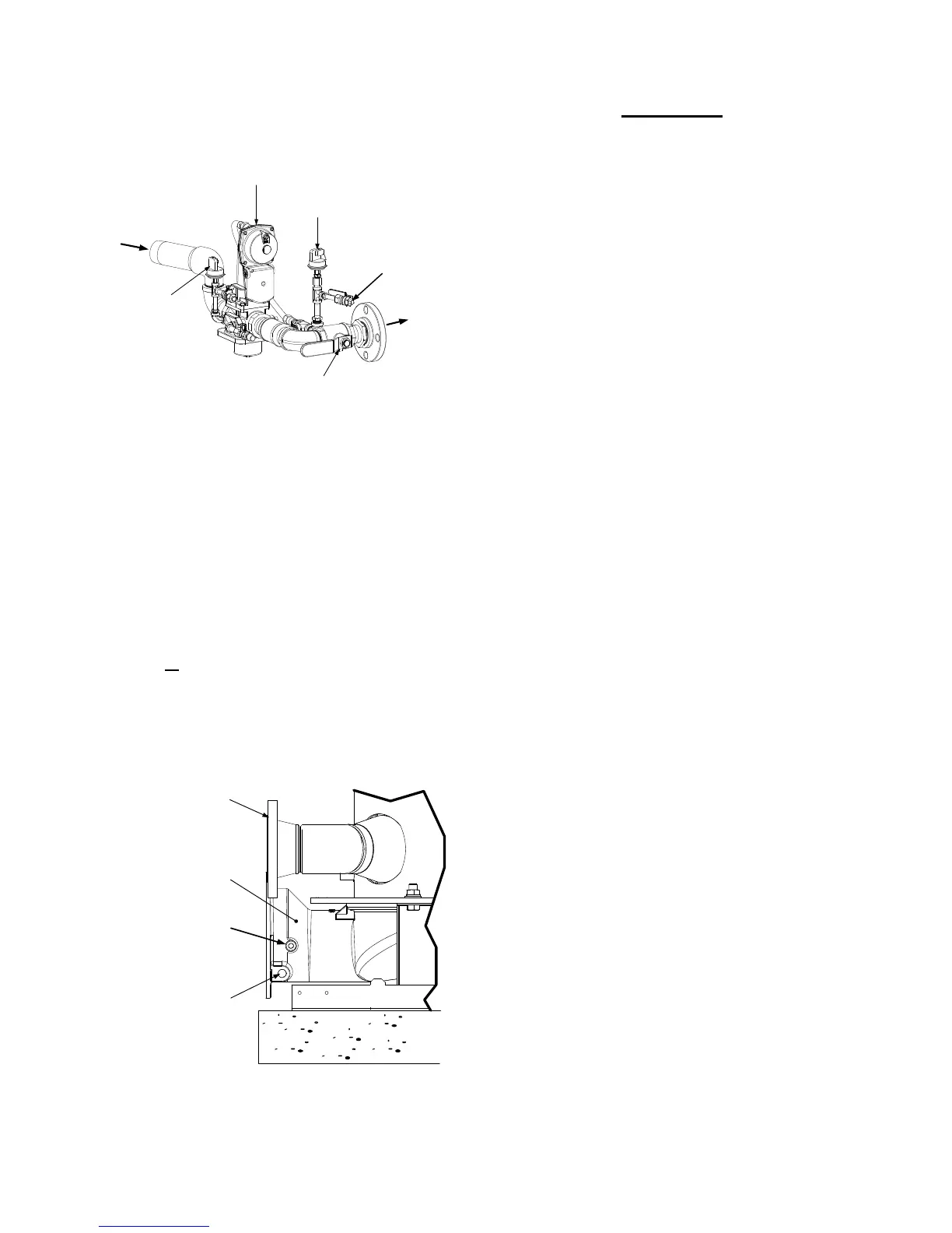
4.2.3 Accessing the Analyzer Probe Port
The unit contains NPT plugs on the left and right
side of the exhaust manifold at the rear of the
unit as shown in Figure 4-2. Prepare the port for
the combustion analyzer probe as follows:
1. Remove the plug from the probe port on the
left or
right side of the exhaust manifold.
2. If necessary, adjust the stop on the
combustion analyzer probe so that it will
extend mid-way into the flue gas flow. DO
NOT install the probe at this time.
EXHAUST
MANIFOLD
1/2” NPT
CONDENSATE
DRAIN
CONNECTION
BOILER
RETURN
ANALYZER
PROBE PORT
Figure 4-2
Analyzer Probe Port Location
IMPORTANT
The unit is shipped from the factory set up
for either Natural Gas or Propane as
specified by the Style No. on the Sales
Order.
If Propane is being used, proceed directly
to Propane calibration procedures in
paragraph 4.4.
4.3 NATURAL GAS COMBUSTION
CALIBRATION
The Benchmark 2.0LN Boiler is combustion
calibrated at the factory prior to shipping.
However, recalibration as part of initial start-up
is necessary due to changes in the local altitude,
gas BTU content, gas supply piping and supply
regulators. Factory Test Data sheets are
shipped with each unit. These sheets must be
filled out and returned to AERCO for proper
Warranty Validation.
It is important to perform the following procedure
as outlined. This will keep readjustments to a
minimum and provide optimum performance.
1. Open the water supply and return valves to
the unit and ensure that the system pumps
are running.
2. Open the natural gas supply valve(s) to the
unit.
3. Set the control panel ON/OFF switch to the
OFF position.
4. Turn on external AC power to the unit. The
display will show LOSS OF POWER and the
time and date.
5. Set the unit to the Manual Mode by pressing
the AUTO/MAN key. A flashing Manual
Valve Position message will be displayed
with the present valve position in %. Also,
the MANUAL LED will light.
6. Adjust the air/fuel valve position to 0% by
pressing the ▼ arrow key.
7. Ensure that the leak detection ball valve
down-stream of the SSOV is open.
8. Set the ON/OFF switch to the ON position.
9. Change the valve position to 29% using the
▲ arrow key. The unit should begin its start
sequence and fire.
10. Next, verify that the gas pressure
downstream of the SSOV is 2.8” W.C. for
both FM and IRI gas trains. If gas pressure
adjustment is required, remove the brass
hex nut on the SSOV actuator containing the
4-2