MC2: 10/03/12 Page 36 of 90
AERCO International, Inc. • 100 Oritani Dr. • Blauvelt, NY 10913 • Ph: 800-526-0288
Modulex MLX Series Gas Fired Boiler System
Operation and Maintenance Manual
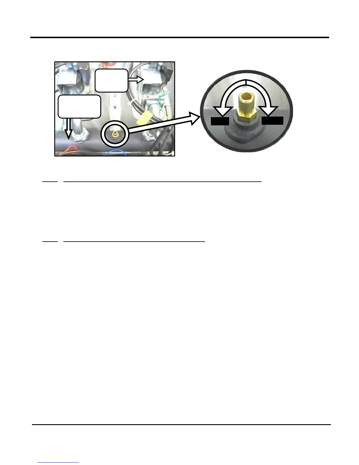
Figure 7-1: Gas Pressure Tap Location and Orientation
7.5.3 Preparing The Flue For Use With The Combustion Analyser
In order to provide an opening for the combustion analyser, proceed as follows:
• If there is no combustion analyser port available, you will have to drill a 3/8” hole in vent pipe,
approximately 2 feet above boiler exhaust manifold.
• If necessary, adjust the stop on the combustion analyser probe so that it will extend mid-way into
the flue gas flow. DO NOT install the probe at this time.
7.5.4 Supply Gas Pressure Check & Adjustment
The optimum gas pressure for the Modulex Boiler is 7.0” W.C. and is used as the desired pressure in
the Combustion Calibration procedures in Paragraph 7.5.5. However, it should be noted that the
Modulex Boiler can be safely operated at gas pressures ranging from 4.0” W.C. (minimum) to 14” W.C.
(maximum) as specified in the Gas Supply Design Guide, GF-115-G.
An external gas pressure regulator is mandatory for the state of Massachusetts. For all applications, a
lock-up style regulator is required when supply gas pressure is greater than 14” W.C. In order to ensure
that the supply gas pressure is adequate for installation, the pressure must be checked under full-fire
conditions using procedures as outlined in the instructions on the following page.