MC2: 10/03/12 Page 45 of 90
AERCO International, Inc. • 100 Oritani Dr. • Blauvelt, NY 10913 • Ph: 800-526-0288
Modulex MLX Series Gas Fired Boiler System
Operation and Maintenance Manual
Chap 8: Safety
Device Testing
8.6 FLAME FAULT TESTS
Flame faults can occur during ignition or while the unit is already running. It is necessary to perform the
flame fault test using the GENERAL/SERVICE/CASCADE MANU menu, where the each burner may be
selected and the valve position set open by a user specified percentage. To simulate each of these fault
conditions for all two to seven burners (depending on model), proceed as follows:
Flame Fault Tests
1. Set the ON/OFF switch to the ON position to start the E8 controller, then select the
GENERAL/SERVICE/CASCADE MANU menu, choose Burner 1, and set the valve position between
25% and 30%.
2. Disconnect the cable from the Burner 1 flame detector at front of unit (see Figure 8-4).
3. The unit should shut down after reaching the ignition cycle and display fault code E4 in the E8
controller display. The E4 fault code indicates a failure to fire at startup.
4. Plug the flame detector cable back onto the Burner 1 flame detector connector.
5. Reset the error displayed in the E8 controller (see paragraph 8.2 for instructions).
6. Use the E8 controller to select the GENERAL/SERVICE/CASCADE MANU menu, choose Burner 1,
and set the valve position between 25% and 30%.
7. After the unit establishes a flame and runs for about a minute, unplug the Burner 1 flame detector
cable at front of unit. The unit should shut down and display a fault code of “E5” on the E8 controller
display. The E5 fault code indicates a loss of flame while running.
8. Plug the flame detector cable back onto the flame detector.
9. Reset the error displayed in the E8 controller (see paragraph 8.2 for instructions).
10. Place the unit in the AUTO Mode and the unit should now restart and fire normally.
11. Repeat the above procedure for each of the unit’s burners.
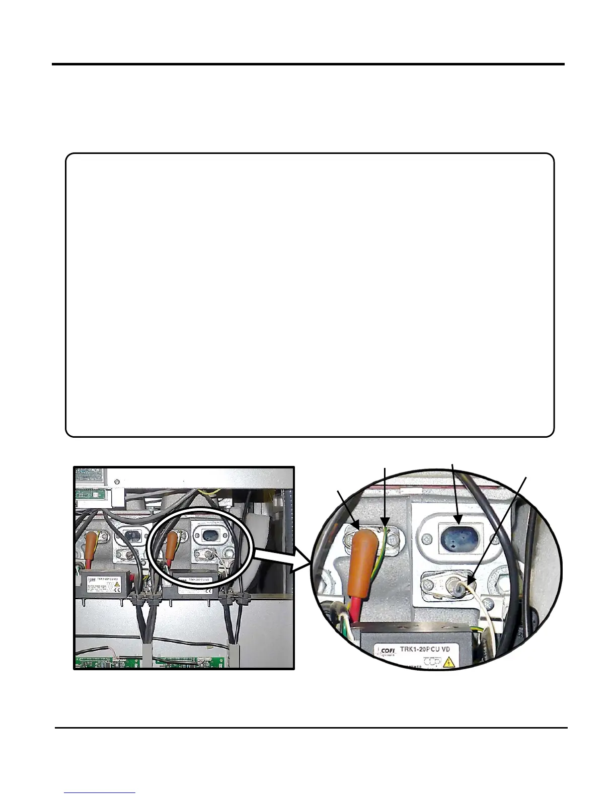
Figure 8-4: Flame Detector and Ignition Component Locations
Igniter
Cable
MLX Rear with Panel Removed
Detector