18
English
AGLLRIJ 0907 - 4528560_03
"GLL10R" INSTALLATION
1
2
3
- Open the packaging of the accessory,
flow frame and intake grid unit, remo-
ve the grid from the packaging and
check that it has not been damaged
during transport.
- Open the cover of the terminal board
on the electric box. Use a tool to rele-
ase the pressurised hooks.
- Connect the power supply cables to
the terminal board as indicated in the
wiring diagram.
- Fix all cables using the cable gland.
- Close the cover of the electric termi-
nal board.
- Check and, if necessary, reset the Dip-
Switches on the electric box accor-
ding to desired functions. (See settings
table)
- Insert the electric box into the FCL
unit guide and make sure that the
connectors are well attached.
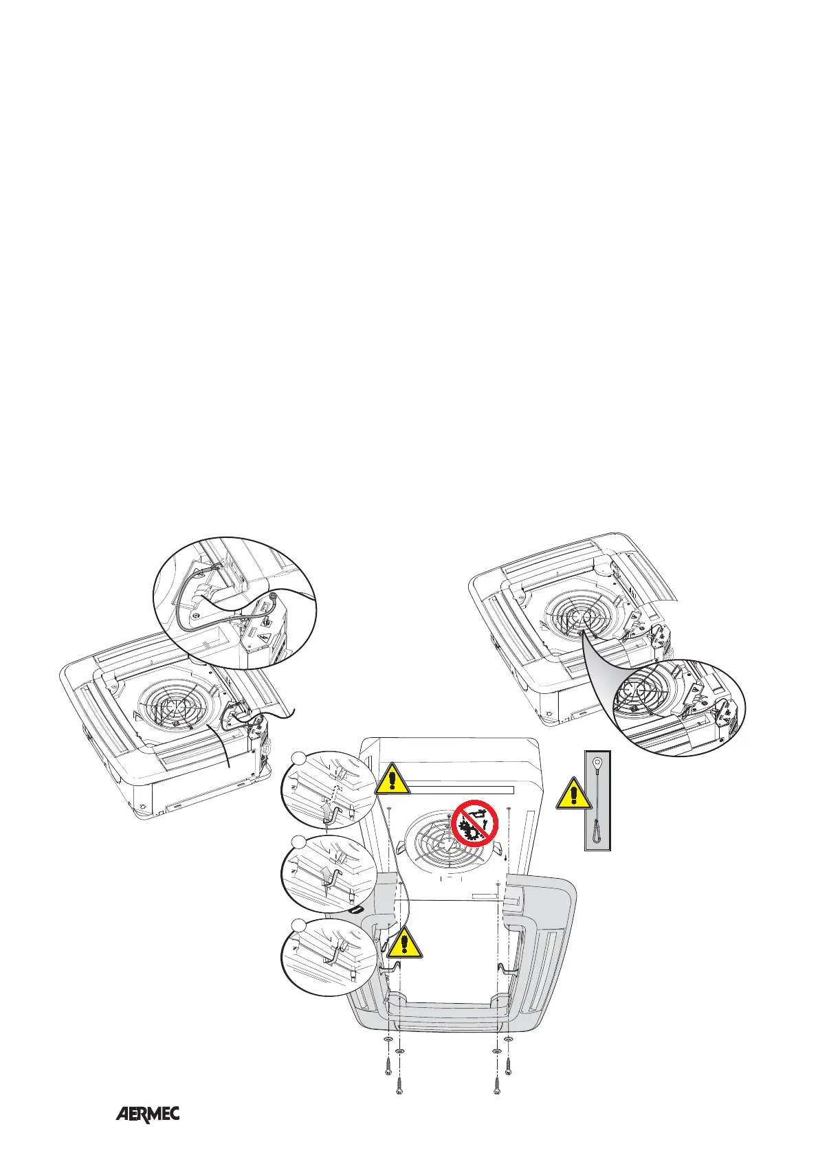
- The electric box must be fixed to the
FCL unit using two screws. The screw
on the attachment side is also used to
fix the supplied safety cable.
ATTENTION: fix the safety cable to
the electric box screw fastener posi-
tioned at the side of the hydraulic
connections. The safety cable snap
hook must then be attached to the
grid frame.
- Apply the air probe (SA) to the centre
of the fan grid, fix the cable using the
supplied straps, lay the excess cable in
the grooves made in the polystyrene.
- Connect the SA probe to the connec-
tor on the electric box.
- Remove the intake grid by acting on
the 2 ratchets by ¼ of a turn.
- To make fixing of the frame to the fan
coil easier, insert two support hooks to
the relevant pegs on the conveyor.
- Hang the frame on the two support
hooks, pay attention to the assembly
position, the corner of the frame with
the AERMEC logo holder must coin-
cide with the corner of the FCL unit
electric box.
- ATTENTION: fix the safety cable to
the frame.
- Connect the receiver connection
cable to the connector on the circuit
board box.
- Fix the frame to the unit using the 4
screws supplied.
CAUTION!! tighten the screws with
maximum coupling torque of 0.45
Nm. It is advised to use a screwdri-
ver, do not use non calibrated electric
screwdrivers. An excessive coupling
torque will damage the tray irrepara-
bly.
The frame guarantees sealing between
air intake and flow, therefore, it must
be fixed correctly to the unit without
undergoing deformations.
- Fix the intake grill to the safety cable.
- Mount the intake grid, hooking it to
the hinge on the frame.
- Close the intake grid and tighten the
two ratchets (on the side opposite the
hinge) by ¼ of a turn.
- Adjust the position of the unit by the
support bracket by means of the nuts,
in a way that the unit is level and the
frame rests slightly in the suspended
ceiling.
- Insert the supplied batteries into the
remote control.
- Start the fan coil and carry out a fun-
ctioning test. The functions are descri-
bed in the user manual.