24
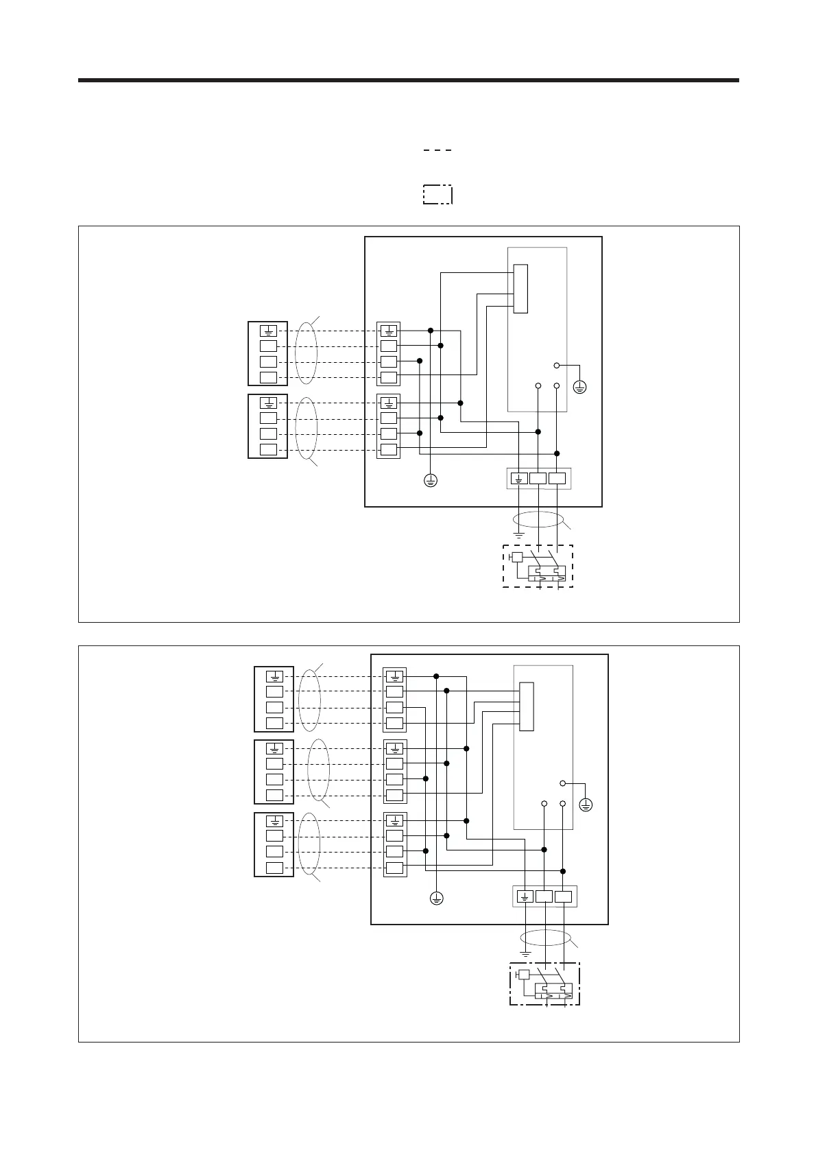
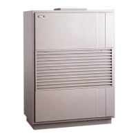
SCHEMI ELETTRICI • WIRING DIAGRAMS
Gli schemi elettrici sono soggetti ad aggiornamento; è opportuno fare riferimento allo schema elettrico allegato all’apparecchio.
Wiring diagrams may change for updating. It is therefore necessary to refer always to the wiring diagram inside the units.
Sez. 1,5 mm
Sez. 1,5 mm
Sez. 2,5 mm
Sez. 1,5 mm
Sez. 1,5 mm
Sez. 2,5 mm
Sez. 1,5 mm
IG = Interruttore generale • Main switch
M = Morsettiera • Terminal board
PE = Collegamento di terra • Earth connection
SC = Scheda di controllo • Electronic control board
=Collegamenti da eseguire in loco
On-site wiring
= Componenti non forniti • Components not supplied
LEGENDA • READING KEY