20
INSTALLAZIONE DELL’UNITÀ ESTERNA
L’unità esterna va installata all’aperto, in posizione perfetta-
mente orizzontale, rispettando gli spazi tecnici minimi per
consentire il passaggio dell’aria e l’esecuzione di eventuali
manutenzioni.
L’unità è costruita con materiali trattati per resistere alle
intemperie e quindi non è necessario proteggerla in modo
particolare. Verificare, invece, che la batteria di scambio
termico non sia esposta al pericolo di grandine.
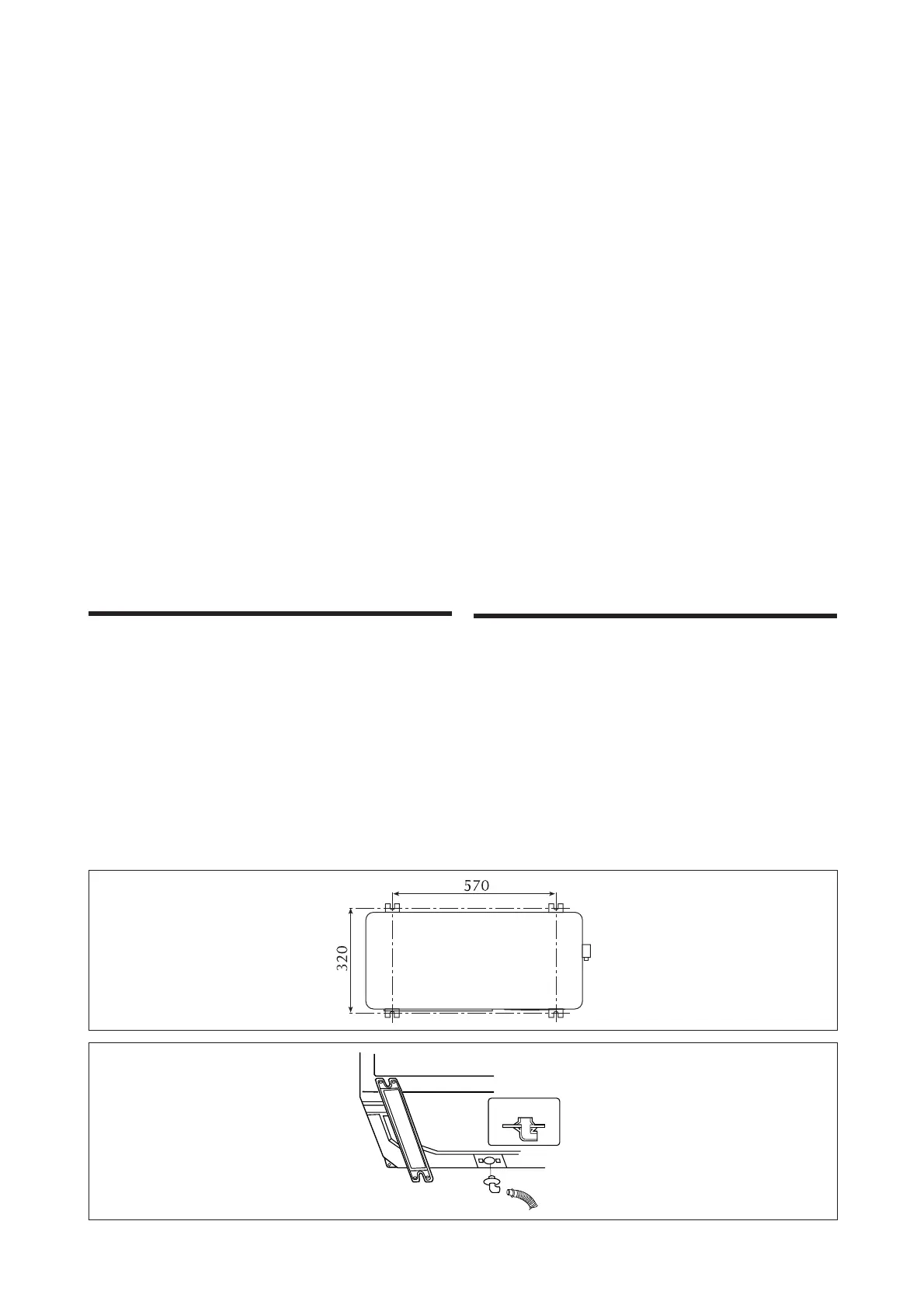
Se si desidera fissare l’unità ad un muro, utilizzare staffe di
dimensione adeguata per sostenere il peso dell’unità. Nel
funzionamento in riscaldamento, viene prodotta dell’acqua,
pertanto, con l’unità fissata a muro, è necessario raccogliere
l’acqua per convogliarla allo scarico (fig. 11).
OUTDOOR UNIT INSTALLATION
Outdoor units must be installed horizontally outdoors in
accordance with the minimum working dimensions to ensu-
re the passage of air and the execution of any necessary
maintenance work.
The unit is constructed in weather-resistant materials and
consequently requires no special protection.
Make sure however that the heat exchange coil is not expo-
sed to the risk of hail storms.
If you wish to mount the unit on the wall use brackets of a
suitable size to support the weight of the unit. . Water is pro-
duced during heating, which, in the case of wall-mounted
installations, must be collected and conveyed to the drain
(fig. 11).
Per il montaggio procedere come segue:
– posizionare la piastra di supporto sulla parete;
– segnare la posizione del foro per il passaggio delle tuba-
zioni (fig. 9);
– segnare la posizione dei fori per i tappi ad espansione;
– eseguire il foro per il passaggio delle tubazioni e dei cavi
elettrici; (se il muro è molto spesso eseguire prima un foro
centrale con una punta lunga e poi allargarlo con una fresa);
– fissare la piastra di supporto al muro;
– svitare le viti e togliere l’involucro dell’unità interna (fig. 4);
– piegare i tubi di rame sull’unità interna secondo le esigen-
ze (fig. 7);
– passare le linee frigorifere attraverso il foro;
– togliere le protezioni dalle estremità delle linee;
– aggangiare l’unità interna al supporto (fig. 8) infilando i
tubi e i cavi elettrici di collegamento tra le unità nel foro.
– collegare le linee frigorifere;
– serrare i cavi elettrici di collegamento tra le unità (fig. 3)
sulla morsettiera dell’unità interna;
L’unità interna viene fornita di serie con il tubo di scarico
condensa collegato a sinistra (vista dal retro dell’unità), ma
è possibile spostare l’attacco a destra. In questo caso biso-
gna scollegare il tubo ruotando in senso antiorario l’attacco;
estrarre, dal lato opposto, il tappo. Inserire l’attacco del
tubo a destra e ruotare in senso orario; inserire una chiave
con testa ad esagono incassato (diagonalmente 4 mm) nel
tappo ed inserirlo a pressione.
To install the unit proceed as follows:
– place the holding plate to the wall;
– mark the hole for the lines (fig. 9);
– mark the holes for the expansion bloks;
– drill the hole for the lines and the electric cables
(if the wall is very thick make a central hole first with a
longer tip and then widen it with a milling machine);
– fix the plate to the wall;
– unscrew the screws and remove the casing of the indoor
unit (fig. 4);
– fasten the cables (fig. 3) to the indoor unit terminal board;
– shape the copper tubes by the indoor unit as required
(fig. 7);
– pass the refrigeration lines through the hole;
– remove the protections from the ends;
– hook the indoor unit to the shelf (fig. 8) and insert the
tubes and cables accross the hole.
– connect the lines;
– hook the indoor unit to the shelf (fig. 3) and insert the
tubes and cables accross the hole.
The indoor unit is supplied as standard with a condensate
drain pipe with left connection (looking at the back of the
unit), but it may be moved to the right coupling. In this case
the pipe must be disconnected by turning it anticlockwise,
then extract the cap from the opposite side, fit the pipe cou-
pling and turn it clockwise. Insert an Allen key (diagonal 4
mm) in the cap and push it in.
Fig. 11
Fig. 10