31
Aermec cod. INRLLSIY 13_01. 4086991_00
NRL 800 - 1800
GB
A
B
C
D
E
F
I
H
G
into menus.
menus.
represent. Once the desired icon is selected the chosen menu is en-
procedures”.
Index Icon Menu Menu function
A
--- MAIN The screens in this menu display the current conditions of the unit (unit status, setpoints,circuit data, etc.)
B
This menu contains advanced information on the unit operation
C
This menu permits the unit to be enabled or disabled, and provides information on the status
D
SYSTEM This menu permits the selection of the operating modes, the water setpoints and the time-clock for the system
E
RECOVERY If the unit includes heat recovery, this menu permits the setting of the parameters associated with the heat recovery
F
INSTALLER
This menu contains the settings useful for the installer (enabling digital inputs, BMS configuration, control, pumps, etc.)
WARNING: This menu is password protected. The password is: 0000
G
ASSISTANCE This menu is only accessible to qualified personnel
H
FACTORY This menu is only accessible to qualified personnel
I
CLOCK This menu contains the clock settings for the system control (date, hour, calender)
1
2
capable of, for the correct use of the unit, are:
(1) Moving from one menu to the next.
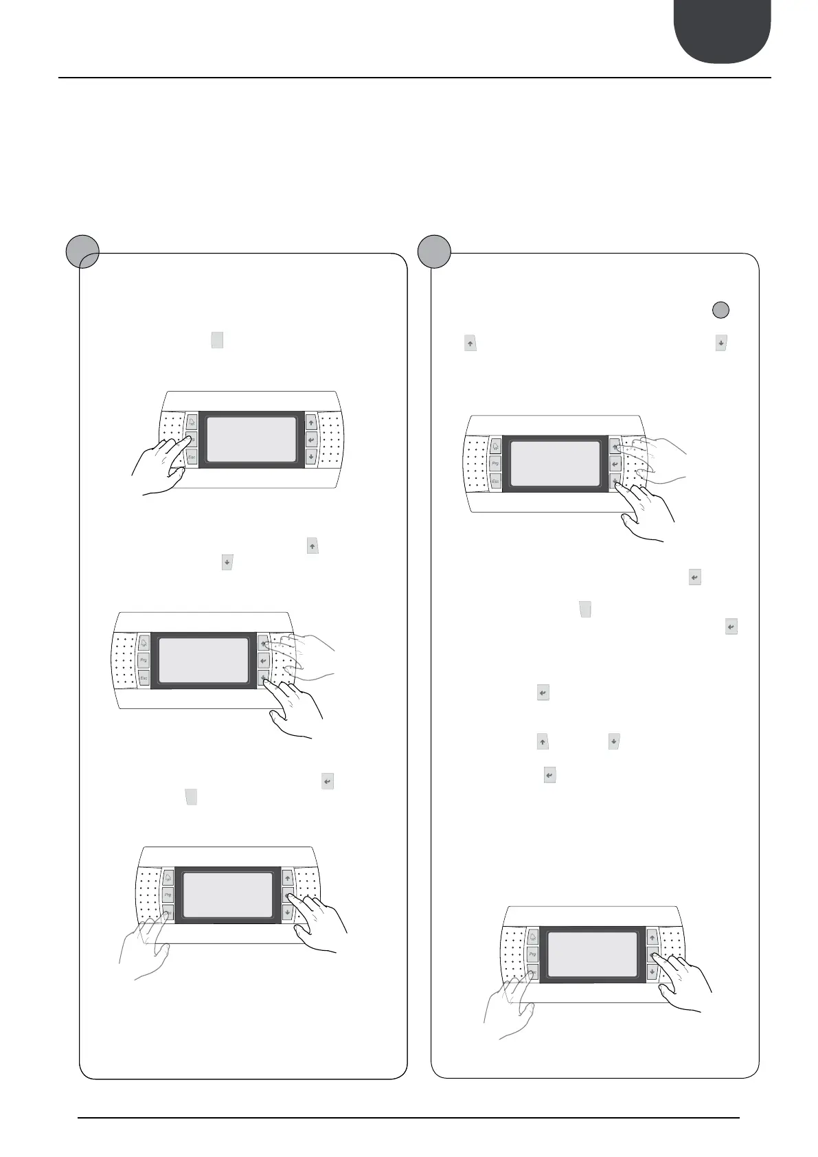
User operating procedures
Moving between menus
(a) To move between the menus, the order in which they are dis-
played is shown in the previous page, enter the menu selection
mode by pressing the key (
).
(b) Once in the menu selection mode it is possible to move
between menus using the arrow keys: the key (
) to move to the
previous menu, and the key (
) to move to the next menu.
(c) When the desired menu is seen press the key (
)to enter the
menu. Press the key(
) to return to the menu selection mode.
Selecting and modifying a menu
(a) Once in the menu selected, by following the procedure (
1
), it
is possible to move between the screens using the arrow keys: the
key (
) to move to the previous parameter, and the key (
) to
move to the next parameter.
(c) When the desired parameter is seen press the key (
) to enter
the parameter. To exit the parameter and return to the parameter
selection mode press the key (
).
WARNING: Once a parameter is selected by pressing the key (
),
the parameter selection mode is automatically accessed and in this
mode the desired parameter values can be set with the following
procedure:
(1) Pressing the key (
) causes a flashing cursor to appear on the
first modifiable field of the parameter. If no modifiable fields are
displayed then the cursor will not appear.
(2) Pressing the key (
) or the key (
), the value of the field can
be increased or decreased.
(3) Pressing the key (
) confirms the modification of the field
value, saving it in memory. On the basis of the type of parameter
selected the number of modifiable fields can change.
previous menu
next
menu
exiting a menu
entering a
menu
previous para-
meter
next
parameter
exiting a
parameter
entering a para-
meter
16. USER OPERATING PROCEDURES
 Loading...