33
Aermec cod. INRLLSIY 13_01. 4086991_00
NRL 800 - 1800
GB
Fig. 1
PR
0
1
M7 SC
6 x 0,5 MAX 50m
7
6
6
5
5
4
4
3
3
COMANDO A DISTANZA
REMOTE CONTROL
2
2
1
1
IAD
ALARM
CONNECTION TO THE POWER SUPPLY
Accertarsi che non ci sia presenza di tensione sulla linea elet-
trica a cui vi allaccerete.
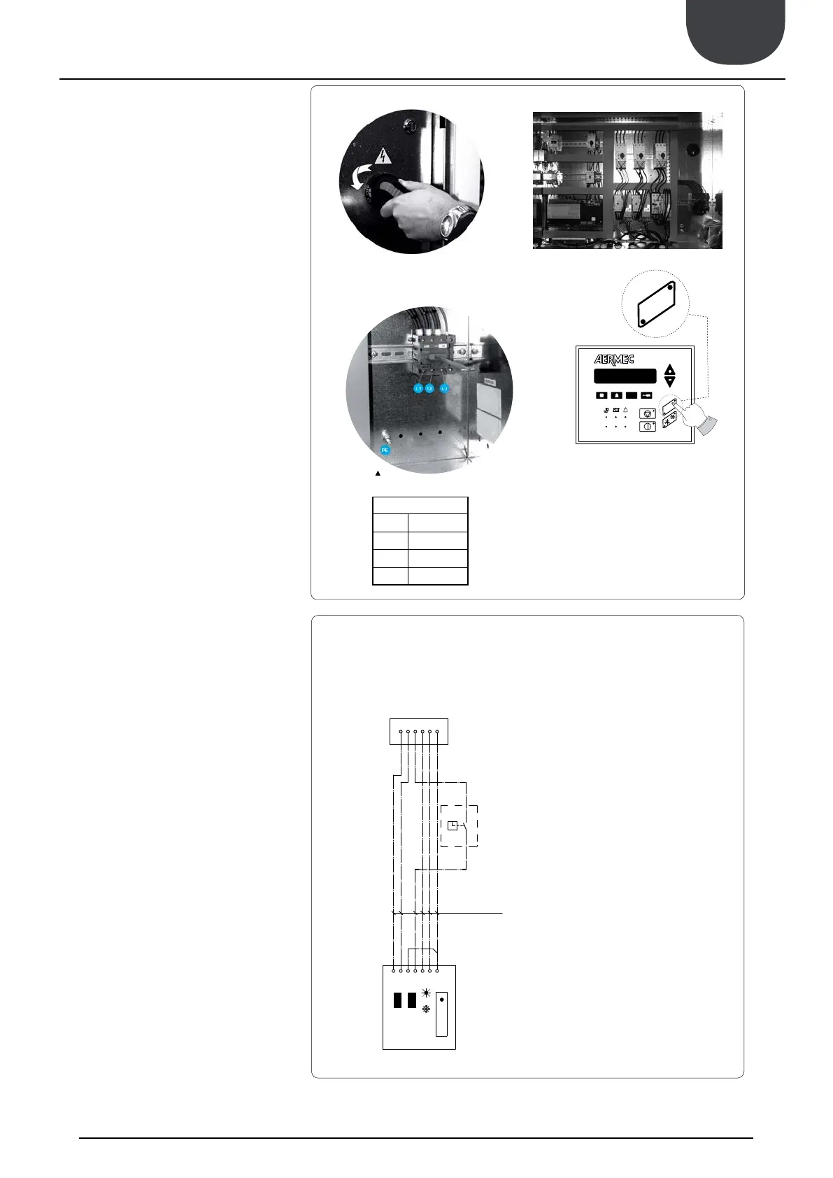
TO ACCESS THE ELECTRIC BOX
Turn ¼ the screws of the electrical panel in counter-clockwise
In this way, the electrical panel can be accessed
ELECTRICAL POWER CONNECTION
power cable to the electrical panel inside the unit in
switch terminals observing the phase, and the earth.
AUXILIARY CONNECTIONS AT THE
USER/INSTALLER EXPENSE
the wiring diagram supplied with the unit.
The wiring diagram together with the manuals must be kept
AUXILIARY SWITCH (IAD)
To prepare the auxiliary switch, connect the device
to the clamp 4 of the control board M7 SC and to the
clamp 4 of the remote panel.
PUMP CONTACTOR (CP01 - CP02)
To prepare the pump contactor, connect the device
CP01 to the clamp 2 of the control board M16 SC and
the device CP02 to the clamp 4 and 6 of the control
board M1 SE2.
EXTERNAL ALARM (EA)
To prepare an external alarm device, connect the
device contact to the clamp 1 and 2 of the control
board M17.
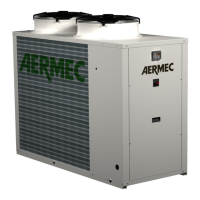
CONNECTION PR3 (STANDARD)
Connect the remote panel PR3 to the control board M7
SC (as shown below),
remember that the maximum allowed distance is 50 m.
THE PR3 CONNECTED MUST BE ENABLED, AS WELL.
See next procedure.
ENABLING
REMOTE PANEL - PR3
To enable the remote panel PR3:
above)
enabled by the remote panel.
CONNECTION
REMOTE PANEL - PR3
L1 Line 1
L2 Line 2
L3 Line 3
PE Earth