45
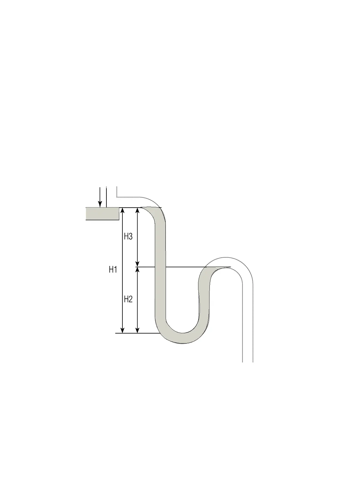
Siphon dimensioning layout
P
POS
CONNECTION INSTALLATION
AERAULIC CONNECTIONS
ATTENTION!
It is prohibited to start the machine if the fan vents are not ducted or
protected using an accident-prevention net.
To install the ducts, it is recommended to:
• prepare adequate bracketing to support the ducts so that the
recovery unit does not bear their weight;
• connect the ow and return vents to the ducts placing anti-
vibration joints in between (duck). The anti-vibration joint must be
screwed to the panel with self-threading screws avoiding that the
duck joints are taut during operation;
• provide an earth cable as a bridge on the anti-vibration joint to
guarantee equipotentiality between the ducks and the recovery
unit;
• prepare (before curves, branches, etc.) the ow duct with a straight
tract measuring at least 2.5 times the smallest side of the duct, A,
to prevent the ducting from having inclinations in the branching
tracts that exceed 7° so that the fan does not lose eciency.
Hydraulic connections: condensate draining
The condensate drip tray is equipped with a 1/2” -G UNI 338 threaded
outlet.
A drain system must envision a suitable siphon to:
• allow free draining of the condensate;
• prevent the undesired entry of air into the depression systems;
• prevent the inltration of smells or insects.
The siphon must have a bleed plug on the bottom or must however
allow quick disassembly for cleaning.
The following rules must be followed to dimension and execute the
siphon (see gure 21):
H1 = 2P
H2= H1 / 2
where P is the pressure expressed in mm of a column of water (1 mm c.w. =
9.81 Pa).