18
18.03. 5719210_03
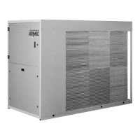
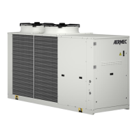
ANL / 290-650
EN
AllelectricalworksmustbecarriedoutbyPERSONNELWITHTHEAPPROPRIATELEGALQUALI-
FICATIONS,trainedandawareoftherisksrelangtosuchworks.
ThedesignofthecablingandrelatedcomponentsmustbecarriedoutbyPERSONNELWITH
APPROPRIATE QUALIFICATIONS TO DESIGN ELECTRICAL INSTALLATIONS, following interna-
onalandnaonalstandardsofthelocaontheunitisinstalled,inaccordancewithcurrent
legalrequirements.
Forinstallaondetailsrefertothe electricalwiringschemacssuppliedwiththe unit. The
electrical wiring schemac together with the manuals must be conserved with care and
MADEAVAILABLEFORFUTUREREFERENCE.
Theweatherproofsealsoftheequipmentmustbecheckedbeforemakingelectricalconnec-
onsandtheunitmostonlybepoweredoncompleonofallelectricalandhydraulicworks..
WARNING:
WARNING:
Verifythatallterminalsaretightonpower
carryingconductorsbeforefirststart-up
and30daysafterputtingintoservice.
Afterwardschecktwiceyearly.
Looseterminalscanresultinoverheating
ofcablesandcomponents..
L.R.A.
L.R.A.
IL
2
2
2
290 400V/3N/50Hz 2 4 130 99 47.1 3+N 1 10 5 1 10 63
300 400V/3N/50Hz 2 4 131 101 50.3 3+N 1 10 5 1 10 63
340 400V/3N/50Hz 2 4 162 123 56.0 3+N 1 16 5 1 16 80
400 400V/3N/50Hz 2 6 183 140 65.9 3+N 1 16 5 1 16 100
580 400V/3N/50Hz 2 2 262 198 84.8 3+N 1 25 5 1 16 125
620 400V/3N/50Hz 2 2 308 230 99.1 3+N 1 35 5 1 16 125
650 400V/3N/50Hz 2 2 320 242 111.7 3+N 1 35 5 1 16 160
L1 L2
400V/3N/50Hz
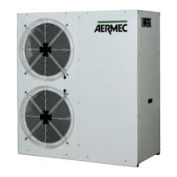
TheANLunitsarefullyfactorywiredandonlyrequire
connecontothepowersupplynetwork,downstream
ofanisolator,inaccordancewiththeapplicablewiring
standardsofthecountryofinstallaon.
Itisrecommendedtocheckthefollowingitems:
1. Theelectricalnetworkiscapableofmeetingthe
electricalinputdatashowninthetablebelow.
2. Theunitisonlypowereduponcompletionof
anyhydraulicandelectricalworks.
3. Complywiththeindicatedphasingandearth
requirements.
4. Thepowersupplycablemusthavetheappropri-
ateprotectionagainstshortcircuits,residual
currentandearthleakagewithsuitableisolation
fromotherdevices.
5. Thetoleranceonthepowersupplyvoltageis
±10%ofthenominalvoltageratingoftheunit
(forthreephaseunitsamaximumimbalanceof
3%betweenphasesispermitted).Ifthesevalues
arenotmetpleasecontactthepowersupply
company.
6. Fortheelectricalconnectionsusedoubleinsu-
latedcablesinaccordancewithapplicablewiring
standards.
1. Amagneto-thermalcircuitbreakerconforming
toIEC-ENstandards(contactapertureminimum
3mm)isrequired,withadequateprotectionin
accordancewiththedataprovidedinthefollow-
ingtable,tobeinstalledascloseaspossibleto
theunit.
2. Aneffectiveearthconnectionisrequired.The
manufacturercannotbeheldresponsiblefor
anydamagescausedbylackof,orinadequate,
earthingoftheunit.
3. Forthreephaseunitscheckthecorrectcable
phasing.
Thecablecrosssectionsshowninthefollowingcable
aretherecommendedvaluesbasedonamaximum50
mcablelength.
Forlongercablelengthsordifferenttypesofcable
installations,theDESIGNERisresponsibleforcorrectly
sizingtheisolator,circuitbreaker,earthingprotection
andcablesizes,basedon:
• Length
• Typeofcable
• Electricalinputoftheunit,distanceandoperat-
ingambients.
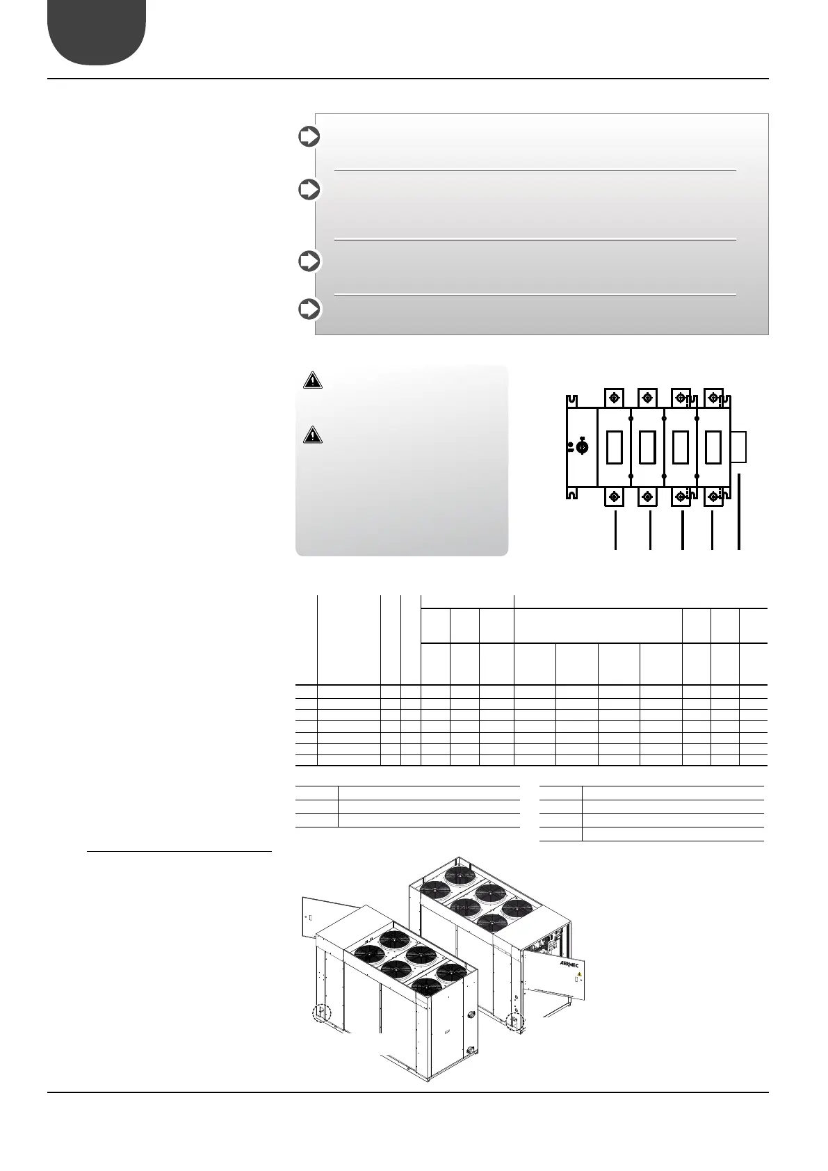
1. Beforemakingtheelectricalconnecons
ensurethattheisolatorisopen.
2. Openthefrontcontrolpanel.
3. Usetheholesprovidedinthelowerpartofthe
cabinetfortheelectricalpowersupplyandfor
otherexternalwiringconnecons.
4. Entercablesintothecontrolpanelonlythrough
theaperturesprovided.
5. Avoiddirectcontactwithun-insulatedcopper
tubesandcompressors.
6. Idenfytheterminalsforelectricalconnecon
withreferencetothewiringdiagramprovided
loosewiththeunit.
7. Takethepowercableintothecontrolpaneland
connecttoterminalsU-NandPEwithrespect
Maximumcurrentinput
Startingcurrent
Powersupplyconnection
3+N: 3phase+neutral
Control+safetiesconnection
Earthconnectiontotheunit
Mainisolator