Subject to Export Control, see Cover Page for details. 1-7
B. Keypad PCB Assy (62A1A2A1)
The Keypad PCB Assy controls the ON/OFF status of the Test Set and the manipulation of the
screens and menus. When a key is pressed, the Multi-Function PCB Assy interacts with the RF
Digitizer PCB Assy and RF Assy to display or manipulate the data on the LCD Display.
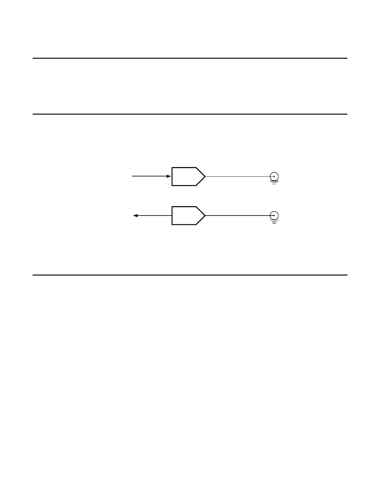
C. RF Digitizer PCB Assy (62A1A2A2) (Figure 1-4)
The RF Digitizer PCB Assy is used for generating the source 10.5 MHz (± 500 kHz) output at
approximately -10 dBm from the DUC (Digital Up Converter), while the receive input to the A2D is
optimized for an input level of -10 dBm at 13 MHz (± 500 kHz). All other RF signaling, filtering,
scaling and up/down conversion methodologies are accomplished in the RF Assy.
TX
DAC
RCV
ADC
TX IF
RCV IF
MULTI-FUNCTION
PCB ASSY
MULTI-FUNCTION
PCB ASSY
Figure 1-4. RF Digitizer PCB Assy Block Diagram
D. Multi-Function PCB Assy (62A1A2A3) (Figure 1-3)
The Multi-Function PCB Assy provides processor control of various digital, analog and RF sub-
circuits used to generate or receive RF signaling normally used in mobile radio communication. The
Multi-Function PCB Assy also contains the application specific circuits to control the other
assemblies. These circuits include interfaces to the LCD Assy, Keypad PCB Assy, Ethernet/RS-232/
USB, Power Supply PCB Assy, RF Digitizer PCB Assy, Audio I/O (3500A only) and RF hardware.
For the Generator, Audio I/O (3500A) and modulation signals are handled by the FPGA`s TDM
measurement bus. This bus runs at a 50 kHz-sample rate capable of delivering high quality audio to
the DUC (Digital Up Converter). The output of the DUC feeds a 14-Bit DAC for the digital-to-analog
conversion needed to form the output source RF signal.
For the Receiver, the output of the 14-Bit A2D is passed to the FPGA. The FPGA sends the data to
the DDC (Digital Down Converter) IC which processes the demodulation schemes needed and passes
the resultant data to the TDM audio bus for final interpretation by one of the system processors. The
system processors move the resultant modulation data to the LCD where the user can view the final
measurements.