Subject to Export Control, see Cover Page for details. 1-9
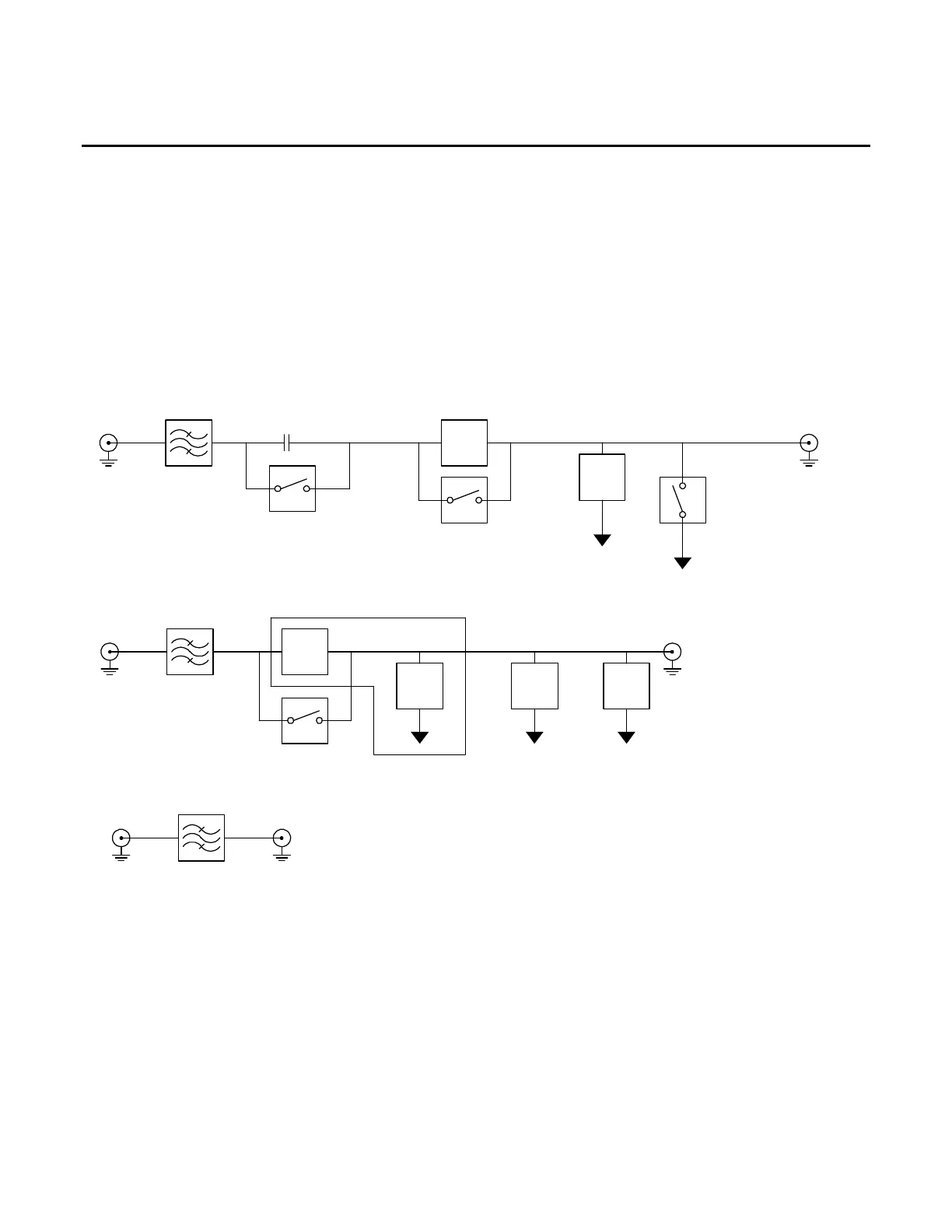
G. Audio I/O PCB Assy (62A1A2A7) (Figure 1-5) (3500A Only)
The Audio I/O PCB Assy provides the DVM/Scope, Audio In and Audio Out signals to the 3500 /
3500A Front Panel.
The "DVM/Scope" input handles ± 40 Vdc through a voltage divider network. AC signals are limited to
1/2 the 50 kHz bandwidth of the TDM audio digitizing bus.
The "Audio In" is specified at 3 Vrms with HIGH Z, 600 Ω or 150 Ω loads available. AM/FM external
signals are limited to 300 Hz to 5 kHz.
The "Audio Out" is rated to deliver 1.57 Vrms into a 600 Ω load with an output impedance of 100 Ω .
Driven by a sample rate of 50 kHz, the specified frequency range is 30 Hz to 5 kHz. The usable
frequency range is 0 to 20 kHz.
Audio In
10 MHz LPF
Div by 1
AC/DC Switch
1.0
M-Ohm
600
Ohm
53.2
k-Ohm
Div by 10
Ground
Switch
10 MHz LPF
From 24 bit D2A 50KSPS
10 MHz LPF
To 16 bit A2D 250KSPS
Scope
150
Ohm
Div by 1
Div by 20
Audio Out
To 24 bit A2D 50KSPS
1.0
k-Ohm
9.0
k-Ohm
Figure 1-5. Audio I/O PCB Assy Block Diagram