2-64 Subject to Export Control, see Cover Page for details.
E. Keypad PCB Assy (62A1A2A1)
DESCRIPTION
This procedure covers: Remove. Install.
PRELIMINARY PROCEDURES
Remove Battery (para 2-4A).
Open Case Assy (para 2-4C).
Remove RF Digitizer PCB Assy (para 2-4F).
Remove Multi-Function PCB Assy (para 2-4G or para 2-4H).
REMOVE
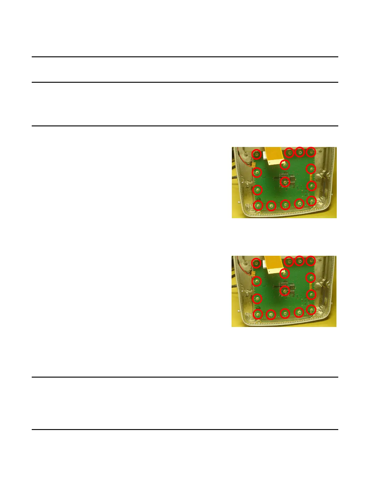
1. Remove 12 screws and five shell nuts.
2. Remove Keypad PCB Assy.
INSTALL
1. Install Keypad PCB Assy.
2. Install 12 screws and five shell nuts (6 in/lbs.).
FOLLOW-ON MAINTENANCE
Install Multi-Function PCB Assy (para 2-4G or para 2-4H).
Install RF Digitizer PCB Assy (para 2-4F).
Close Case Assy (para 2-4C).
Install Battery (para 2-4A).
END OF TASK