AES 7788 Series RF Subscriber Unit ─ Installation and Operation Manual
AES Corporation 12 40-7788, Rev 6, August 30, 2016
2 Commercial Fire and Burglary Installation Notes
UL Burglar Installations Tamper Protection: A UL Listed tamper switch that protects
the cover against opening or removal is required on the 7788F installed in a burglar alarm
installation. If the 7788F is installed outside the protected area, a tamper device is
required to protect the enclosure against removal from the mounting surface.
Use a UL approved plunger type tamper switch, installed using holes drilled by the
installer through the side and rear of the enclosure as suggested in Diagram below. Refer
to diagram below, actual selected UL Listed tamper device and manufactures
documentation for installation instruction and required hole-pattern.
Wire tamper devices to a zone as outlined in the tamper device manufactures
documentation and section 3.
The tamper devices must be installed and wired to activate a zone on the subscriber to
generate an alarm signal at the central station.
In addition to installing tamper devices on the 7788F, a motion detector connected to the
alarm control panel is required to protect the 7788F against attack.
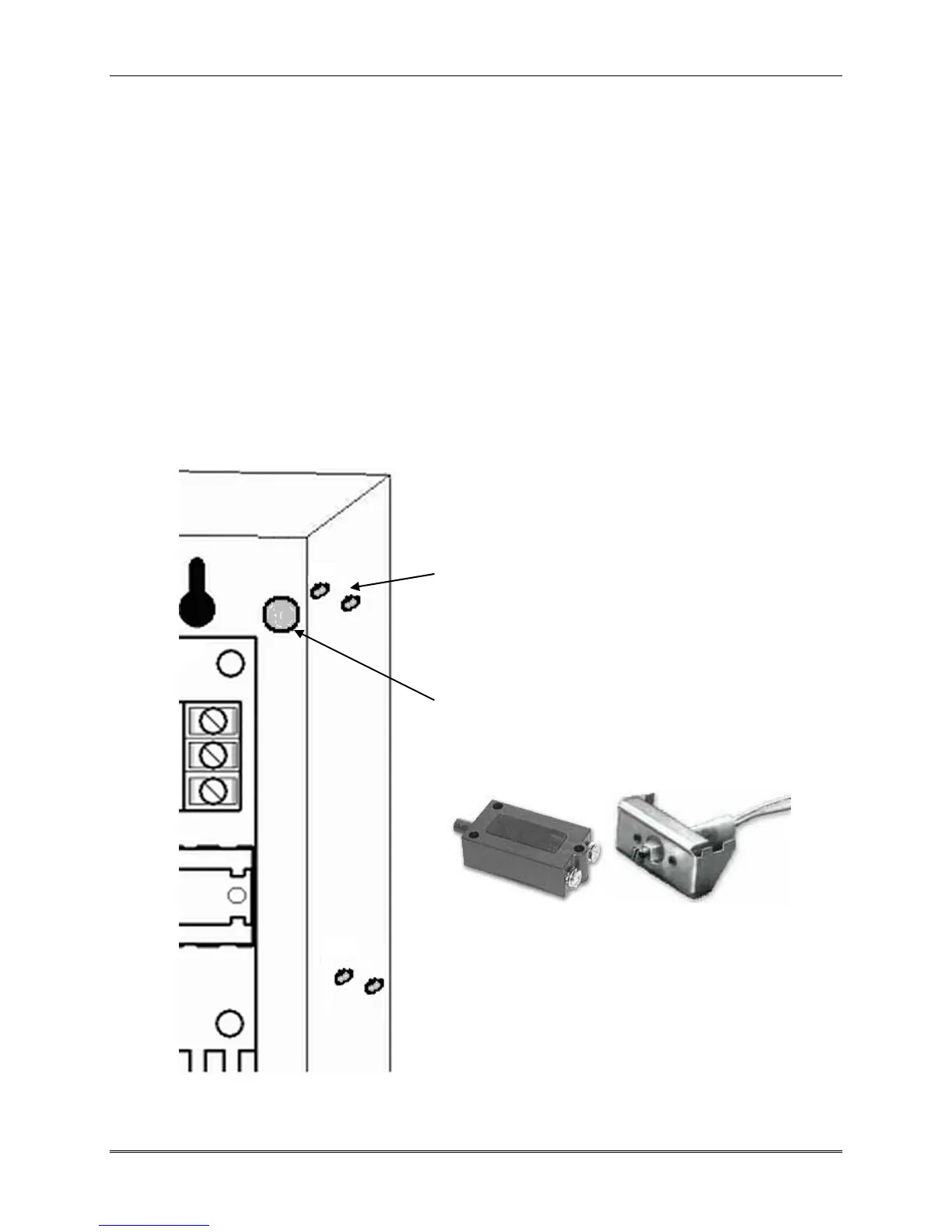
The 5 shaded holes shown in the diagram to the left
indicate suggested locations for holes needed to
install a typical UL Listed plunger type tamper
switch.
Actual dimensions are to be determined from the
actual switch and or switch installation instructions.
Although the typical switch has three mounting
holes available, two are sufficient to securely mount
the switch.
A typical plunger type switch requires a 3/8” hole
centered at the location where the plunger can
protrude unhindered through the rear of the
enclosure to make contact with the enclosure’s
mounted surface.
Several plunger type Tamper switches are shown
above. The switch on the left is the style selected
for the suggested hole patterns in the diagram to the
left. The switch style on the right with built in
mounting flange allows installation of a cover
tamper without the need to drill holes.
Suggested Tamper Switch Mounting Locations