AES 7788 Series RF Subscriber Unit ─ Installation and Operation Manual
AES Corporation 13 40-7788, Rev 6, August 30, 2016
2.1 Power Requirements: 16.5 VAC, 40VA/45VA
For UL certificated burglar alarm installations, use the Listed AMSECO transformer
P/N XF1640, ELK P/N ELK-TRG1640 or TDC Power P/N DA-40-16.5 or MG
Electronics P/N MGT1640
For commercial fire alarm installations in the U.S., use the Listed AMSECO
transformer P/N XF1640, ELK P/N ELK-TRG1640 or TDC Power P/N DA-40-16.5
or MG Electronics P/N MGT1640
Do Not Connect To A Receptacle Controlled By A Switch
2.2 Backup Battery requirement, Commercial Fire
Central Station Fire Signaling (24hr): use a 12V, 7.5 AH battery when using 7744 by
itself. Per this manual, Section 1.4.1, the capacity may need to be as high as 12 Ah
when all modules are used.
Remote Station Fire Signaling (24hr): use a 12V, 7.5 AH battery when using 7744 by
itself. Per this manual, Section 1.4.1, the capacity may need to be as high as 12 Ah
when all modules are used.
2.3 UL 681
Commercial Burglar Alarm Installation (4hr) use 12V, 7.5 AH battery
Replace battery(s) every 3 years
2.4 UL 1610/365
For Burglar Alarm installations the 7788F unit shall be connected to a UL Listed
central control panel such that opening and closing signals are provided.
To provide confirmation of arming signal receipt at the central station, the DACT,
integral with the Listed Control Panel, shall be used for Open/Close Reports.
Set the Report Delay in the 7788F to 0 seconds.
2.5 7788F EOL Inputs / Zones
EOL Alarm Inputs must be programmed for Supervised or Fire.
For UL installations, the wire linking alarm panel must use electrically supervised
inputs (Program the subscriber unit for Supervised or Fire Supervised accordingly).
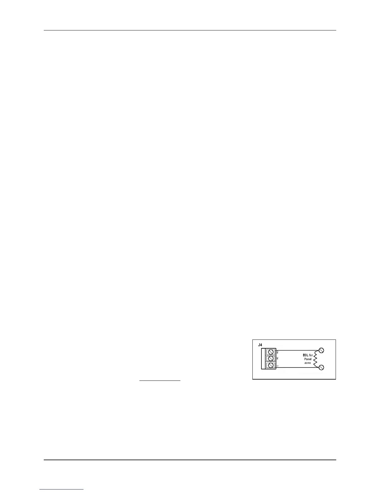
2.6 Local Trouble Output
For RF Type 6 Fire Alarm Systems, and Central
Station / Police Connect Burglar Alarm Systems -
connect the J4 output of the 7788 Subscriber Unit
circuit board to a non-reporting trouble zone on an
FACP or some other method to annunciate the trouble at the premise. Refer to pages
17 & 19 for J4’s location and additional information. Unsupervised. Contact rating
24 VDC, 1-Amp resistive maximum.
The wire connections between the control panel and J4 output must be supervised
against opens, shorts and grounds.