AES 7788 Series RF Subscriber Unit ─ Installation and Operation Manual
AES Corporation 27 40-7788, Rev 6, August 30, 2016
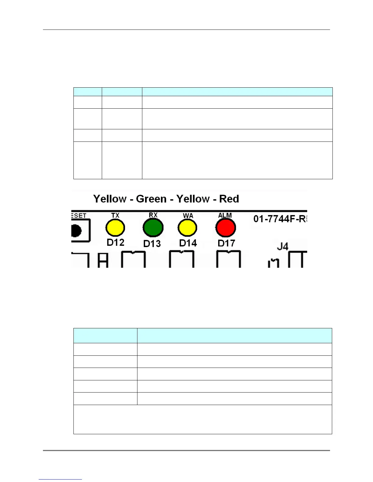
3.9 Status (LED) Indicators
There are 4 LED indicators on the main circuit board of the 7788F.
The function of each is described below.
STATUS INDICATORS: LED's are located near the top edge of circuit board next to
J1/Programmer connector and the Reset button.
Status / troubleshooting indicator, “blink” See chart below
Steady On = Waiting for acknowledgment of last transmission
Steady Blinking = Not on Network; Off = Normal
Illuminated indicates radio transmit
Illuminated indicates radio transceiver receiving RF signal.
Steady on for 20 seconds or more indicates RF interference.
(Includes any radio activity on this frequency strong enough to
break squelch)
Diagram 5 – LED Indicators
3.10 ALM LED Blink Pattern Chart
The chart below shows the various blink patterns utilized by the ALM LED, and what
status conditions the blink pattern indicates.
Short-short blink - low battery
Short-long blink - an input zone is in alarm or trouble
Short-short-long blink, low battery & zone in alarm/trouble
Steady / no blink - Self-test failure (excluding low battery)
Symbols as follows: "●" = short blink, " ▬ " = long blink
Period between patterns is about 1 second with chart showing
pattern repeated 3 times.