AES 7788 Series RF Subscriber Unit ─ Installation and Operation Manual
AES Corporation 18 40-7788, Rev 6, August 30, 2016
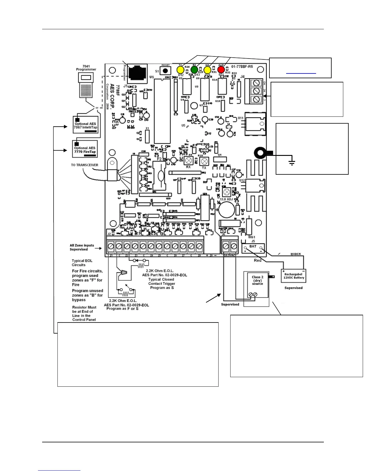
12VDC 250 mA max, Unsupervised
Earth Ground – Green Nut
Use a ring lug connector
and 18 gauge (min) wire to
connect to a suitable earth
ground, such as a
metal cold water
pipe.
3.4 Wiring - General
Diagram below shows details of the 7788F board with some typical wiring examples.
Diagram 3 – User Connections
Terminals on J2 are not sutible for installation of multiple wires. Use a Wire Nut and Pigtail to connect
multiple wires to a single terminal as shown in wiring diagram example above on terminal J2 position “C”.
See additional information on next page
All wiring except the AC must use shielded wires with at least one end of the shield grounded.
Transformer Enclosure
AES 1640-ENCL
With Transformer
Power In: 16.5VAC, 40VA,/45VA
Class 2 (dry) source only.
Use AES p/n 1640, or
Amseco P/N XF1640 or ELK P/N ELK-TRG1640
or TDC Power P/N DA-40-16.5 or MG Electronics P/N
MGT1640
Status Indicators
See Section 3.8
Transformer
Wiring must
be in Conduit
For separation of
circuits, battery
wires are
covered with
Teflon tubing
J4 Antenna Cut / Trouble
Relay output
24 VDC 1 Amp Resistive
Unsupervised
For Wiring Diagram of 7794 IntelliPro Fire
See: 40-7794 -7794 Installation and Operation Manual
For wiring diagram of 7067 IntelliTap See:
40-7067 - AES 7067 IntelliTap-II Manual
For Wiring Diagram of 7770 FireTap See:
40-7770 - 7770 Installation and Operation Manual
For Wiring Diagram of 7762 See 40-7762 – 7762 Installation
and Operation Manual