7
Rear Panel Layout
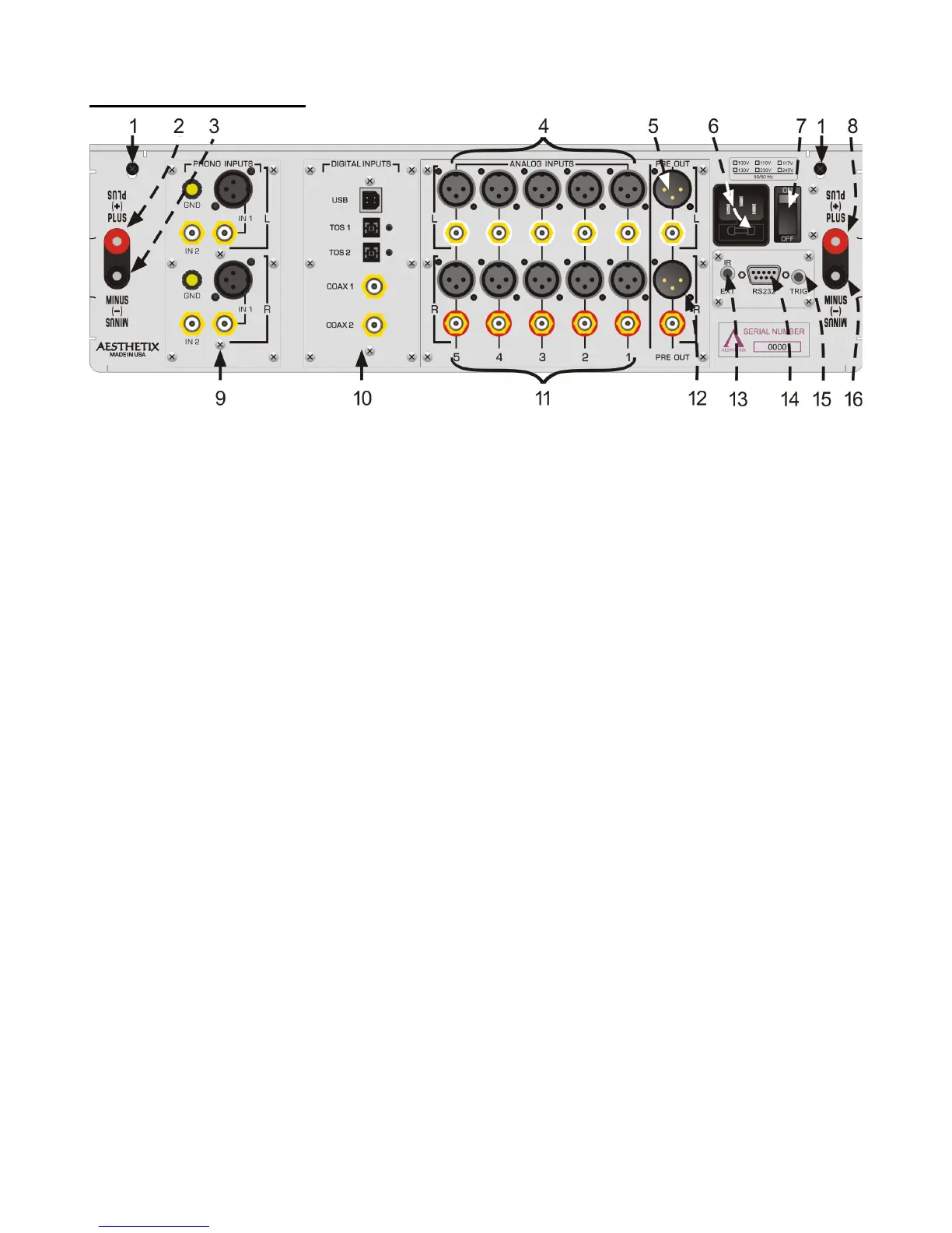
Figure 2 - Rear Panel Layout
1. 6-32 screws to secure the top cover. Before removing top cover, turn off rear panel MAIN POWER switch
and wait 15 minutes. Then remove the two 6-32 screws and pull up top cover from the rear panel.
2. Right channel Plus BINDING POST. Connect plus speaker wire for the right speaker to this terminal.
3. Right channel Minus BINDING POST. Connect minus speaker wire for the right speaker to this terminal. DO
NOT CONNECT TO GROUND.
4. Left channel balanced and single-ended Analog Input jacks.
5. Left channel balanced and single-ended Preamp Output.
6. AC POWER INPUT and main fuse. Spare fuse inside.
7. MAIN POWER Switch. Disconnects AC to all circuits. It is recommended that this be left ON at all times
during regular use with the exception of whenever cables are connected/disconnected or when the unit is not
going to be used for an extended period of time.
8. Left channel Plus BINDING POST. Connect the plus speaker wire for the right speaker to this terminal.
9. Optional Phono Input module.
10. Optional Digital to Audio (DAC) input module.
11. Right channel balanced and single-ended Analog Input jacks.
12. Right channel balanced and single-ended Preamp Output.
13. IR extender input jack. Connect external IR receiver to this input
14. DB9 RS232 connector. Used for connecting a system control device to the Mimas to control and monitor its
functions.
15. Remote Trigger jack. When set to do so, as the Standby button is pressed to take the Mimas out of standby,
the rear panel trigger jack becomes active with a 5 VDC signal. A compatible receiving device such as
another Power Amplifier will receive this signal and then change its mode from standby to operate. When the
Standby button is pressed again the signal goes to 0V and puts the receiving device into standby mode. The
Remote Trigger Jack can also be setup as a trigger input, which when receiving a 5VDC signal, takes the
Mimas out of standby.
16. Left channel Minus BINDING POST. Connect the minus speaker wire for the left speaker to this terminal.
DO NOT CONNECT TO GROUND.