44 microAeth
®
MA Series MA200, MA300, MA350 Operating Manual microAeth
®
MA Series MA200, MA300, MA350 Operating Manual 45
AethLabsAethLabs
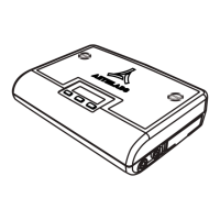
5.8.3.4. Filter Tape Cartridge Removal and Installation
The on-board user interface on the front of the microAeth is used to remove and install the lter tape
cartridge.
1) Make sure that the microAeth is not sampling. If the instrument is sampling, use the on-board interface
to stop sampling and measurements.
2) Unscrew the large at head slotted screw(s) in the lter tape cartridge door of the case. When the
screw is completely free of its mating threaded hole, use the at head slotted screw(s) to pull the lter
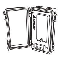
tape cartridge door from the case.
3) The lter tape cartridge will now be exposed or if a lter tape cartridge is not currently installed, the
cartridge holder area will be empty.
4) Use the left and right buttons of the on-board user interface to scroll through the top level menu
options to ‘Release Tape’.
5) Press the center button to select the ‘Release Tape’ option. '-Releasing Tape' will be displayed on the
screen and the optical head of the instrument will move to its open position and stop in about 6 seconds.
6) Once the optical head stops moving, use the pull tab in the center of the lter tape cartridge to remove
the cartridge straight out of the instrument.
7) Insert a new lter tape cartridge straight into the instrument, aligning the left and right holes in the
cartridge with the two white capstans in the instrument.
8) Make sure that the new lter tape cartridge is fully inserted and sits at in the instrument.
9) Use the left and right buttons of the on-board user interface to scroll through the top level menu
options to ‘Clamp Tape’.
10) Press the center button to select the ‘Clamp Tape’ option. '-Clamping Tape' will be displayed on
the screen and the optical head of the instrument will move to its clamped position and stop in about 6
seconds.
11) Conrm that the lter tape cartridge is clamped by the optical head.
12) If the lter tape cartridge is correctly installed, replace the lter tape cartridge door to its closed
position and completely screw the large at head slotted screw(s) in place. Once the door is in its closed
and locked position, the instrument is ready for further use
13) If the lter tape cartridge is not fully installed or seated properly in the instrument after clamping the
tape, use the left and right buttons to scroll through the top level menu options to ‘Release Tape’. Press
the center button to select the ‘Release Tape’ option. If the instrument does not accept the release tape
command, press and hold down the center button until the optical head moves up enough to remove the
lter tape cartridge. Then remove the lter tape cartridge. Use the left and right buttons to scroll through
the top level menu options to ‘Clamp Tape’. Press the center button to select the ‘Clamp Tape’ option.
The optical head of the instrument will move to its clamped position and stop, resetting the optical head
position. Go to step 4 and try again to replace the lter tape cartridge.
5.8.3.5. Calibrate Flow
IMPORTANT: Please read section 7.3. Flow Calibration and section 7.3.5. Flow Calibration
Procedure before using this menu option. The only way to perform a ow calibration on the MA200,
MA300, and MA350 is to use a microAeth MA Series Flow Calibration Kit provided by AethLabs.
Before starting the automatic ow calibration process, the lter tape cartridge must be at a new clean
lter sampling location. The microAeth should be plugged into an external power source. The only way
to perform a ow calibration on the MA200, MA300, and MA350 is to use a microAeth MA Series Flow
Calibration Kit provided by AethLabs.
5.8.3.6. Test Flow
IMPORTANT: Please read section 7.3.3. Test Flow Procedure before using this menu option. This
menu allows the user to change ow setpoint target to 50, 75, 100, 125, or 150 ml/min and to have the
measured ow of the internal owmeter displayed as a comparison to check the quality of the current
FlowCal table calibration of the instrument.
5.8.3.7. Calibrate Optics
IMPORTANT: Please read section 7.4. Optical Calibration Procedure before using this menu option.
Before starting the automatic optical calibration process, the lter tape cartridge must be at a new
clean lter sampling location. The microAeth should be plugged into an external power source. The
optical calibration should be run only when the lter tape cartridge door is installed and closed.
The optical calibration CANNOT be cancelled once it is started.
5.8.3.8. Change Serial Mode
The on-board user interface on the front of the microAeth can be used to change the serial mode setting
of the instrument.
1) Use the left and right buttons to scroll through the top level menu options to the ‘Change Serial Mode’
option.
2) Press the center button to select the ‘Change Serial Mode’ option and to enter the change serial mode
submenu.
3) Use the left or right buttons to scroll through serial mode value options of Off, Streaming, or Polled.
4) Press the center button, 'OK' to select the current serial mode value option. Once selected, the value is
saved and the user interface menu is automatically returned to the top menu level.
5.8.3.9. Change Serial Baud
The on-board user interface on the front of the microAeth can be used to change the serial baud rate
setting of the instrument serial port.
1) Use the left and right buttons to scroll through the top level menu options to the ‘Change Serial Baud’
option.
2) Press the center button to select the ‘Change Serial Baud’ option and to enter the change serial baud
submenu.
3) Use the left or right buttons to scroll through serial baud value options of 57600, 115200, 230400,
460800, 921600, or 1000000.
4) Press the center button, 'OK' to select the current serial baud value option. Once selected, the value is
saved and the user interface menu is automatically returned to the top menu level.
 Loading...