78 microAeth
®
MA Series MA200, MA300, MA350 Operating Manual microAeth
®
MA Series MA200, MA300, MA350 Operating Manual 79
AethLabsAethLabs
ow calibration process will produce the desired ow calibration table. See section 7.3.2. Display and
Check Flow Calibration Table.
7.4. Optical Calibration Procedure
The on-board user interface on the front of the microAeth can be used to start the automatic optical
calibration process.
IMPORTANT: OPTICAL CALIBRATIONS ARE NOT RECOMMENDED UNLESS INSTRUCTED TO DO SO
BY AETHLABS OR AETHLABS AUTHORIZED SERVICE PERSONNEL. Before starting the automatic
optical calibration process, the lter tape cartridge must be at a new clean lter sampling location.
The microAeth should be plugged into an external power source. The optical calibration should be
run only when the lter tape cartridge door is installed and closed. The optical calibration CANNOT be
cancelled once it is started.
1) The microAeth must be at a new clean lter sampling location for the optical calibration.
2) If the microAeth is not already at a new clean lter sampling location, use the left and right buttons to scroll
through the top level menu options to the ‘Advance Tape’ option. Otherwise skip to step 4.
3) Press the center button to select the ‘Advance Tape’ option. The microAeth will advance the lter tape
cartridge to a new clean lter sampling location.
4) Plug in the microAeth to an external power source through the barrel jack port.
5) Make sure the lter tape cartridge door is installed and closed.
6) Use the left and right buttons of the microAeth to scroll through the top level menu options to the ‘Calibrate
Optics’ option.
7) Press the center button of the microAeth to select the ‘Calibrate Optics’ option and to enter the calibrate
optics submenu. ‘YES OK NO’ will be displayed.
8) Press the center button to exit and return to the top level menu.
9) Press the left button 'YES' and the screen will display 'Calibrate? YES'. Press the right button 'NO' and the
screen will display 'Calibrate? NO'.
10) Press the center button, 'OK' to select the current yes or no value option. Once selected, the optical
calibration will start and 'Starting' will be displayed.
11) As the optical calibration progresses, the screen will display 'Calibrating... xxxx' and the 'xxxx' four digit
numbers will be updated.
12) When the optical calibration is complete, 'Calibration Complete' will be displayed and the user interface
menu is automatically returned to the top menu level.
7.5. Installing Operating System Firmware
The on-board user interface on the front of the microAeth can be used to upgrade the operating system
rmware via the 4-pin serial port. Upgrading the operating system rmware of the microAeth can be
accomplished through a terminal emulator using the AethLabs 4-pin Serial to USB converter cable.
Before using the AethLabs 4-pin Serial to USB converter cable, it may be required to install drivers
from Future Technology Devices International Ltd. (FTDI) in order for the converter cable to be
recognized by and used with the computer.
7.5.1. Upgrading firmware from version 1.05 to 1.08
IMPORTANT READ FIRST: ALL DATA ON THE MICROAETH WILL NOT BE ACCESSIBLE AFTER
UPGRADING FIRMWARE. All memory on the microAeth will need to be erased after upgrading the
rmware. Before upgrading the rmware on the microAeth, download and backup all data from the
instrument. A ow calibration and optical calibration may be required after upgrading the rmware.
Make sure that you have a microAeth MA Series Flow Calibration Kit provided by AethLabs as this is
the only way to perform a ow calibration on the MA200, MA300, and MA350.
1) Unplug the microAeth from all external power sources.
2) Plug in the AethLabs Serial to USB converter cable to the 4-pin serial port of the microAeth. Plug in the
USB A plug of the cable into a computer where data will be download.
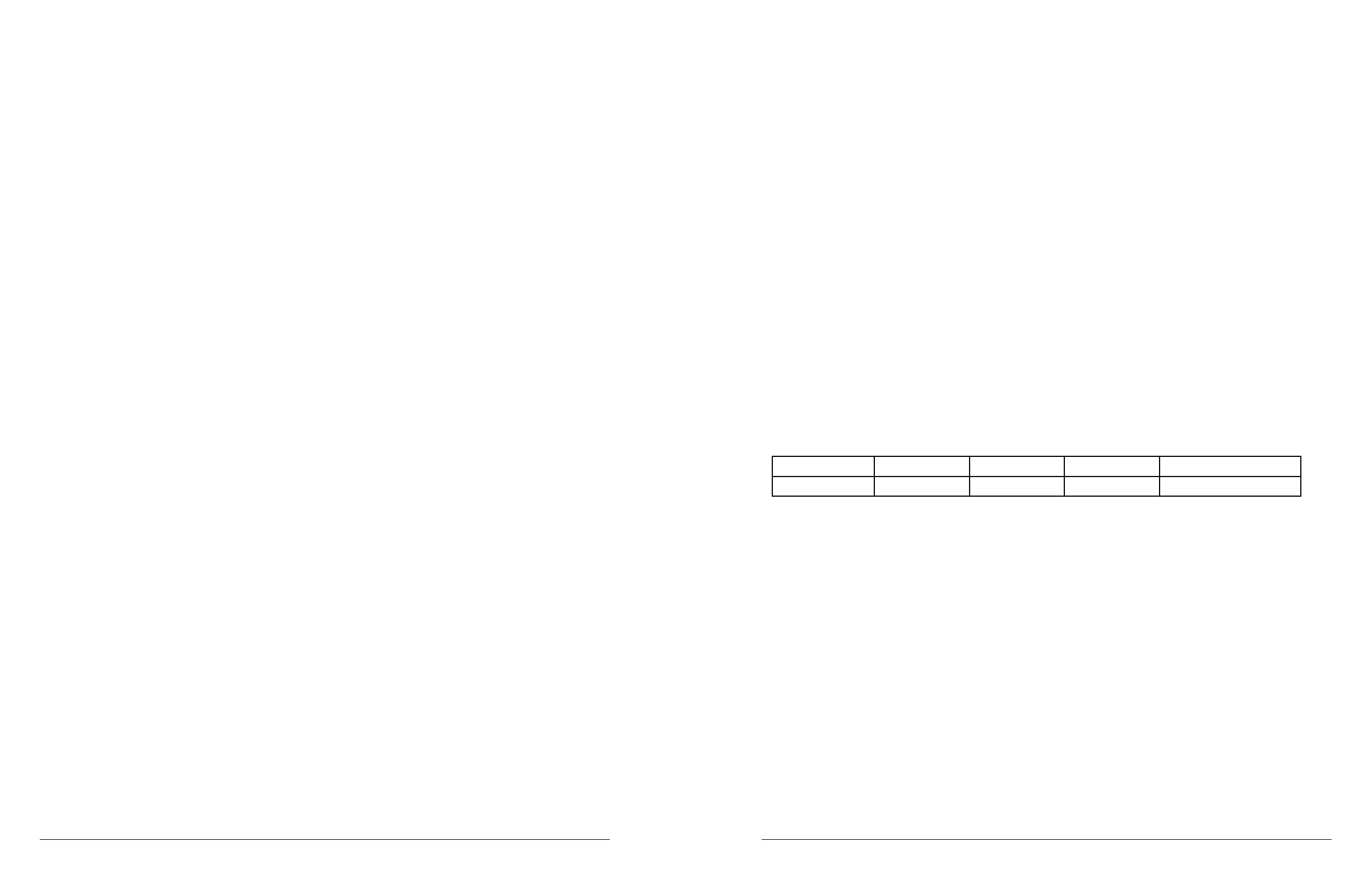
3) Open a terminal emulator (AethLabs only supports Tera Term for Windows) on the computer and use the
following settings (as described in section 5.5.3):
Baud Rate Data Parity Stop Flow control
1000000 8 bit none 1 bit Xon/Xoff
4) When Tera Term opens, a window with the title 'Tera Term: New connection' will appear.
5) Select the 'Serial' radio button.
6) Use the 'Port:' dropdown menu to select the COM port that the microAeth is connected to through the
AethLabs 4-pin Serial to USB converter cable.
7) Press 'OK'.
8) The main window will remain and the window title will now be the COM port number.
9) Select the 'Setup' menu and select 'Serial port...'.
10) In the 'Tera Term: Serial port setup' window, change the settings to match the communication settings
in Step 3.
11) Press 'OK'.
12) The terminal emulator should now display the on-board user interface options as the 3 button interface
is used by the user. More information that is hidden on the microAeth on-board screen will be displayed in
the terminal emulator.
13) Use the left and right buttons to scroll through the top level menu options to the ‘Turn off’ option.
14) Press the center button to select the ‘Turn off’ option.
15) While the microAeth is off, press and hold both the left and right buttons at the same time for about 2
seconds.
16) If successful in entering the bootloader, the screen backlight will ash on three times and stay on.
17) The microAeth will display more information to the terminal emulator.
 Loading...