21
DESN 517179
DESN 516895
DESN 516897
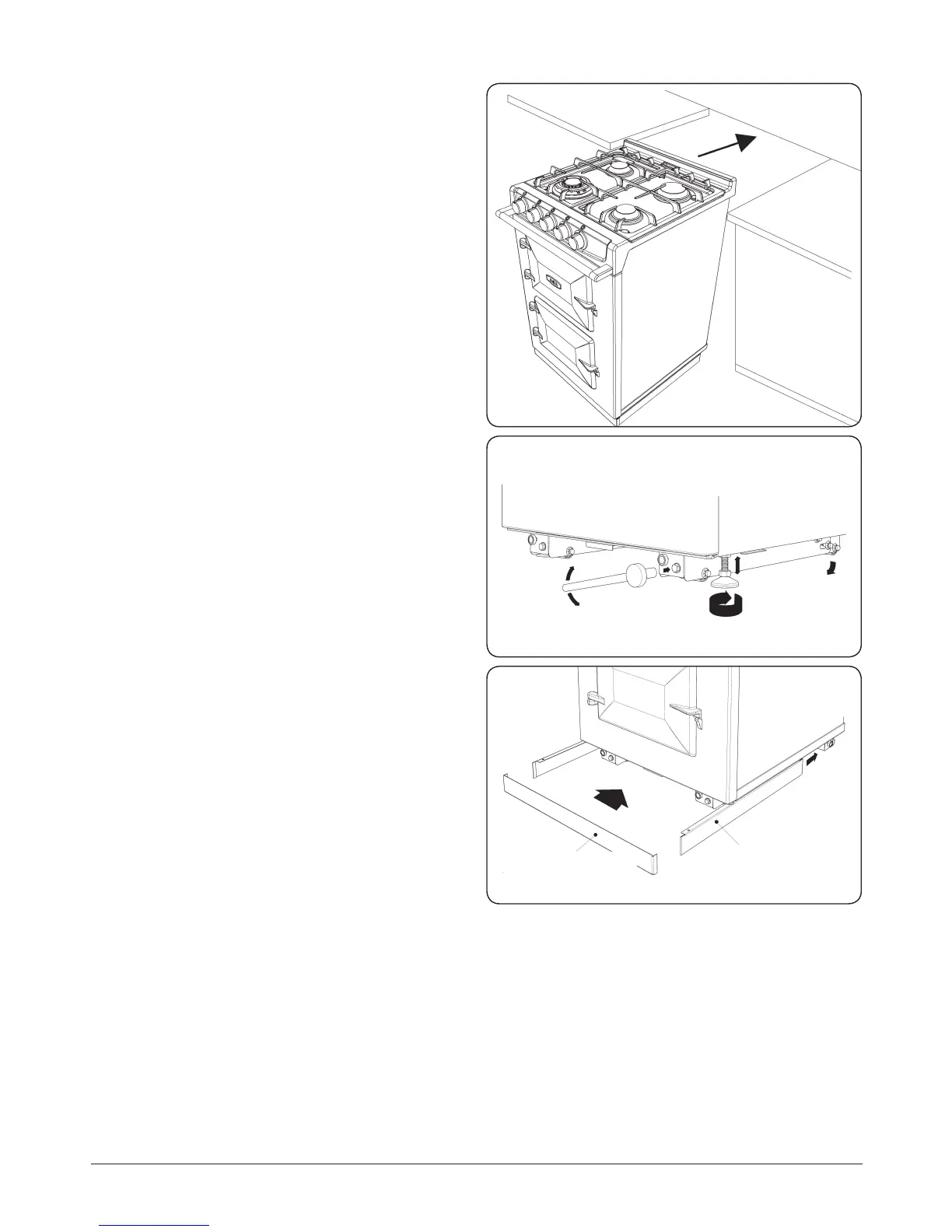
Fig. 11.5
Fig. 11.6
Fig. 11.7
5. Appliance can now be pushed back on its wheels into
desired position. NOTE: Care must be taken not to trap
mains cable (Fig. 11.5).
6. Levelling of appliance - Use 13mm socket to adjust
wheel mechanism for FINE adjustment on both sides at
rear of the appliance (Fig. 11.6).
7. Using a 12mm open end spanner, feet can be adjusted
at front to make FINE adjustments to the front of the
appliance and to provide a brake for the wheels (Fig.
11.6).
8. Turning the bolt clockwise will lower the wheel thus
increasing height of the cooker (Fig. 11.6).
9. Anti-clockwise lifts the wheels and lowers the cooker
(Fig. 11.6).
10. Fit the magnetic plinth (Fig. 11.7)
FRONT PLINTH COVER FITS
OVER SIDE SKIRTS
MAKE SURE SIDE PLINTH
SKIRTS ARE LOCATED IN
FRONT GUIDE BRACKET