DESN 517234
DESN 517564
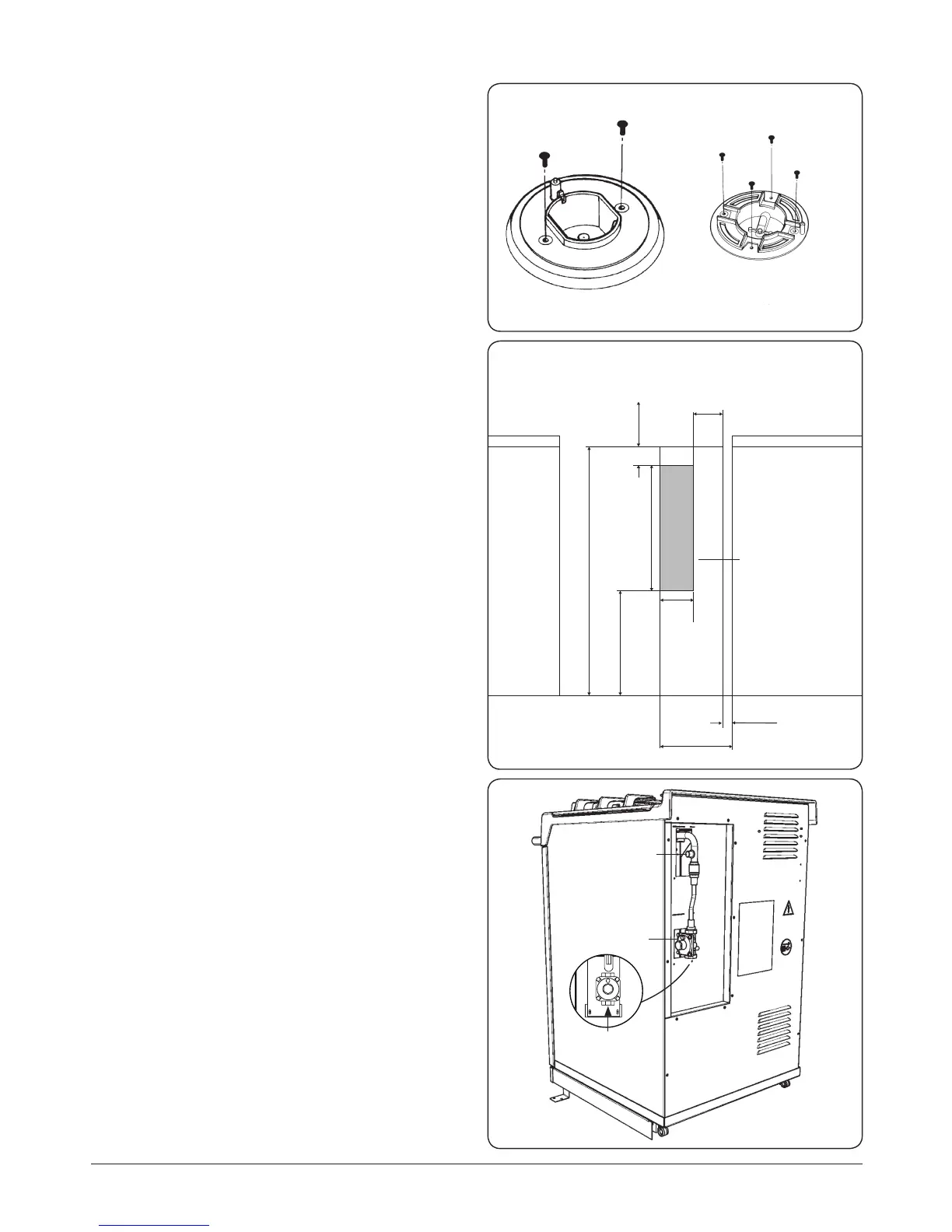
POSITION OF GAS BAYONET ON WALL
(locate in shaded areas)
Pressure
test point
Gas regulator
Inlet
½” BSP Fitting
LOCATION AREA
BAYONET FITTING
Gas connection
CAUTION: ENSURE THAT THE APPLIANCE IS
ISOLATED FROM ELECTRIC SUPPLY
The appliance can be installed with an approved exible
connection. Supply piping should not be less than ⁄ I/D.
Connection is made to the R½(½”BSP) female threaded tting
located just below the hotplate level on the rear right-hand
side of the appliance.
The gas bayonet connector provided, must be tted to the
wall in the shaded area dimensioned in Fig. 14.6. Take into
account that it must be possible to pull the appliance forward
suciently for servicing. Ensure exible hose is not trapped
between appliance back panel and rear wall. Ensure hose is
routed away from the vent slots in the back panel. The exible
hose must be in accordance with the relevant standards.
IMPORTANT: The gas supply connection at the wall
must not project out from the wall by more than
45mm, so that it does not foul with the back of the
appliance Fig. 14.6.
FLEXIBLE HOSE
The exible hose must be suitable with the type of gas being
used. LPG hoses carry a red stripe, band or label. If in doubt
ask your supplier.
For an appliance other than an upright appliance, which may
be connected with a hose assembly. The supply connection
point must be accessible with the appliance installed.
NOTE: Use soapy water solution on new gas connections to
ensure there are no gas leaks.
Check for gas tightness after connecting the appliance.
Pressure testing
NOTE: The regulator is set for N.G. or for Propane X put out of
action.
The pressure test point is situated just below the hotplate
level on the rear right-hand side of the appliance (Fig. 14.5).
• For Natural Gas manifold pressure is 1kPa (4” w.g.)
• For L.P.G. (Propane X Only) manifold pressure 2.54kPa
(10” w.g.).
• Re-fit test point blanking screw and check for gas
tightness.
DESN 511646
(WOK BURNER ONLY)
Fig. 14.4
Fig. 14.5
Fig. 14.6