25
The isolator should not be positioned immediately above
the appliance, but must be tted within 2 metres of the
appliance.
The isolator maybe separate from the connection point.
The mains connection point must be accessible within the
areas (Fig. 13.2) for cable routing options.
A fully recessed cooker connection box may be located
immediately behind the appliance (in the hatched area only
Fig. 13.2) . A gap of 5mm must be allowed at the rear of the
cooker.
For 2 or 3 phase installations an optional adaptor kit must be
obtained (Part No. AE4M280352).
13. Electrical connection
Fig. 13.1
Fig. 13.2
DESN 516918
DESN 517184
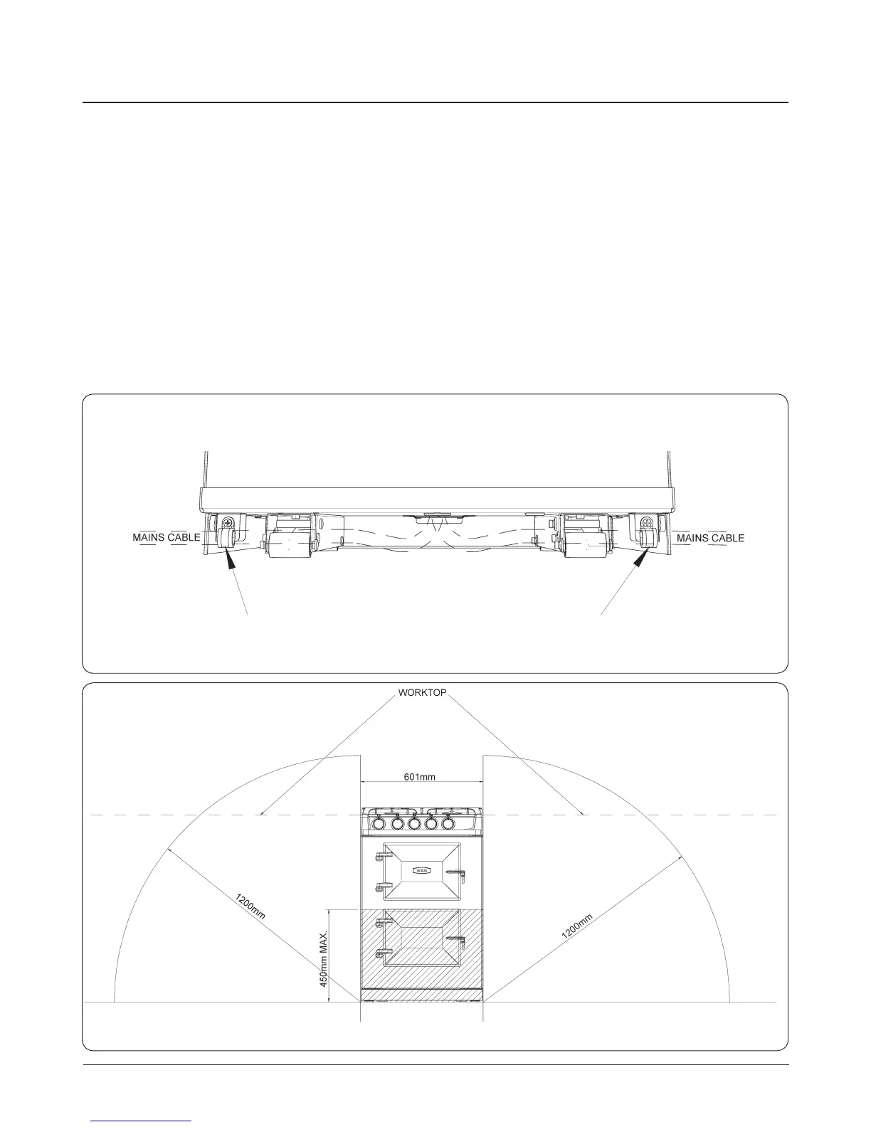
SECURE MAINS CABLE USING ‘P’ CLIPS FOR LEFT HAND OR RIGHT HAND CABLE MANAGEMENT.
THE MAINS SUPPLY MUST BE WITHIN THE ZONES SHOWN. IF A RECESSED COOKER CONNECTION IS TO BE
USED BEHIND THE APPLIANCE WITHIN THE HATCHED AREA ALLOW A 5mm GAP AT REAR OF APPLIANCE.
NOTE: If timer kit is tted use the cable tie provided in
timer kit to secure timer cable to mains cable.
WARNING: THIS APPLIANCE MUST BE EARTHED.
THIS APPLIANCE IS DESIGNED FOR THE VOLTAGE
STATED ON THE RATING PLATE, WHICH IS SITUATED
BEHIND THE PLINTH COVER.
A 1PH 32 amp 240V or 3PH 400V minimum 16A per phase
~ 50 Hz fused electrical supply is required adjacent to the
appliance. External wiring to the unit must be installed using
the mains cable provided, in accordance with the current
wiring regulations and any local regulations which apply. If
cable is shortened, new ferrules must be tted to the stripped
conductors.
The method of connection to the mains electricity supply
must facilitate complete electrical isolation of the appliance,
by a multi-pole switch, having a contact separation of at least
3mm on all poles.