4
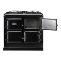
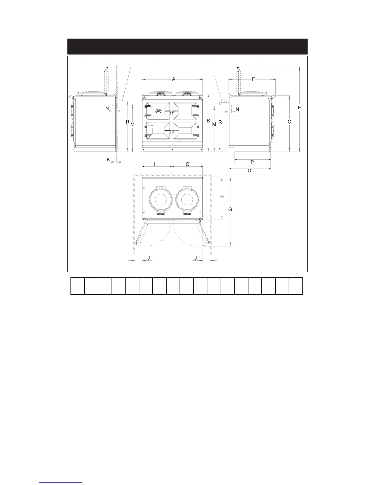
APPLIANCE DIMENSIONS - AGA DC3
Fig. 1 DESN 516358 A
Cooker Dimensions
When surveying for a cooker installation the actual clearance required for the ‘body’ of the
appliance should be increased by 10mm beyond the figures quoted above. This allows safe
margin to take into account the natural dimensional variations found in major castings. In
particular the width across the appliance recess could be critical.
RH SIDE
OVEN VENT
OPTION
RH SIDE VIEW
FRONT VIEW
LH SIDE
OVEN VENT
OPTION
LH SIDE VIEW
PLAN VIEW
MINIMUM WALL POSITION
MINIMUM WALL POSITION
APPLIANCE WEIGHT (Excludes Packaging)
Model: AGA Dual Control (DC3) - 444kg
A B C D E F G H J K L M N P Q R
mm 987 948 910 680 1388 760 1145 698 116 10 536 813 30 634 448 849
REAR OVEN VENT
PIPE POSITION
REAR OVEN VENT
PIPE POSITION
 Loading...