79034308 B Rev. 02-9
General Information
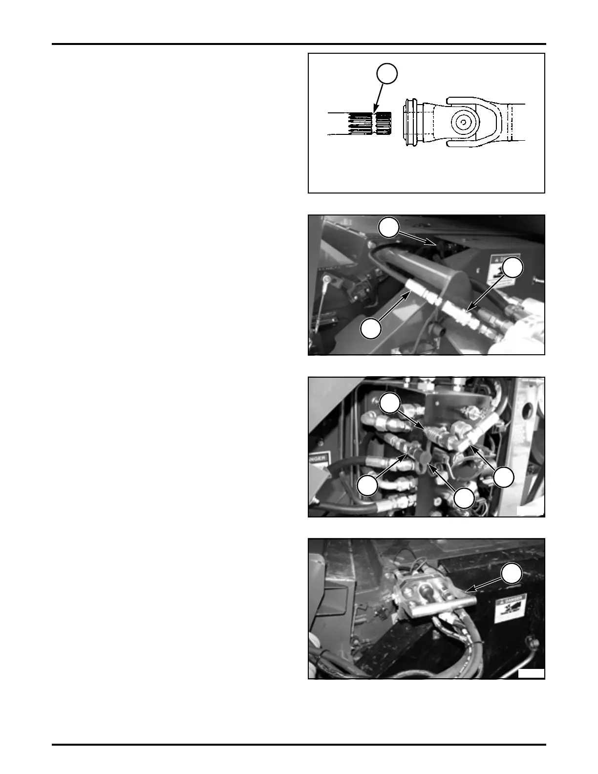
FIG. 19: Release the locking ring and pull back and forth
on the driveline to make sure that the coupling is locked in
the annular groove (1) on the countershaft.
Repeat the procedure for the opposite driveline on dual
knife drive.
IMPORTANT: Be sure that the same letter is showing in
the indicator windows on the PTO bells after the
installation of the left and the right drivelines.
FIG. 20: Transverse Machine - If a corn head has
been attached, install the reel lift hose (1) onto the reel lift
fitting (2) on the single point connector. Make sure the
dust cap (3) is installed on the variable speed fitting.
Move the lockout ring on the variable speed drive sheave,
on the left-hand side of the pivot shafts to the locked
position.
IMPORTANT: When running the grain head, the variable
speed header drive must be locked in the
slowest position. Over speeding will damage the
grain header.
FIG. 21: Axial Machine - If a corn head has been
attached, install the variable speed hose (1) onto the male
coupling fitting (2) in the main hydraulic control valve.
Make sure the dust cap (3) is installed on the variable
speed fitting (4) at the reel lift port.
Move the lockout ring on the variable speed drive sheave,
on the right-hand side of the pivot shaft, to the locked
position.
IMPORTANT: When running the grain head, the variable
speed header drive must be locked in the
slowest position. Over speeding will damage the
grain header.
FIG. 22: Connect the mobile single point connector (1) to
the single point connector on the machine. Align the
connectors and close the over-center latch locking the
connectors together.
NOTE: To install the header on a machine without a
single point connector, and adapter is needed.
Refer to the appropriate sections to set the proper cutter
bar tilt for the drive tires used on the machine, level of the
header, set the auger flighting clearance, draper pressure,
and reel lift cylinder phasing.
m
WARNING: DO NOT operate the machine
unless ALL shields are installed.
FIG. 19
FIG. 20
FIG. 21
FIG. 22
 Loading...