CHAPTER 4
14 AGCO RoGator RG900/1100/1300 Hawkeye™ Installation Manual
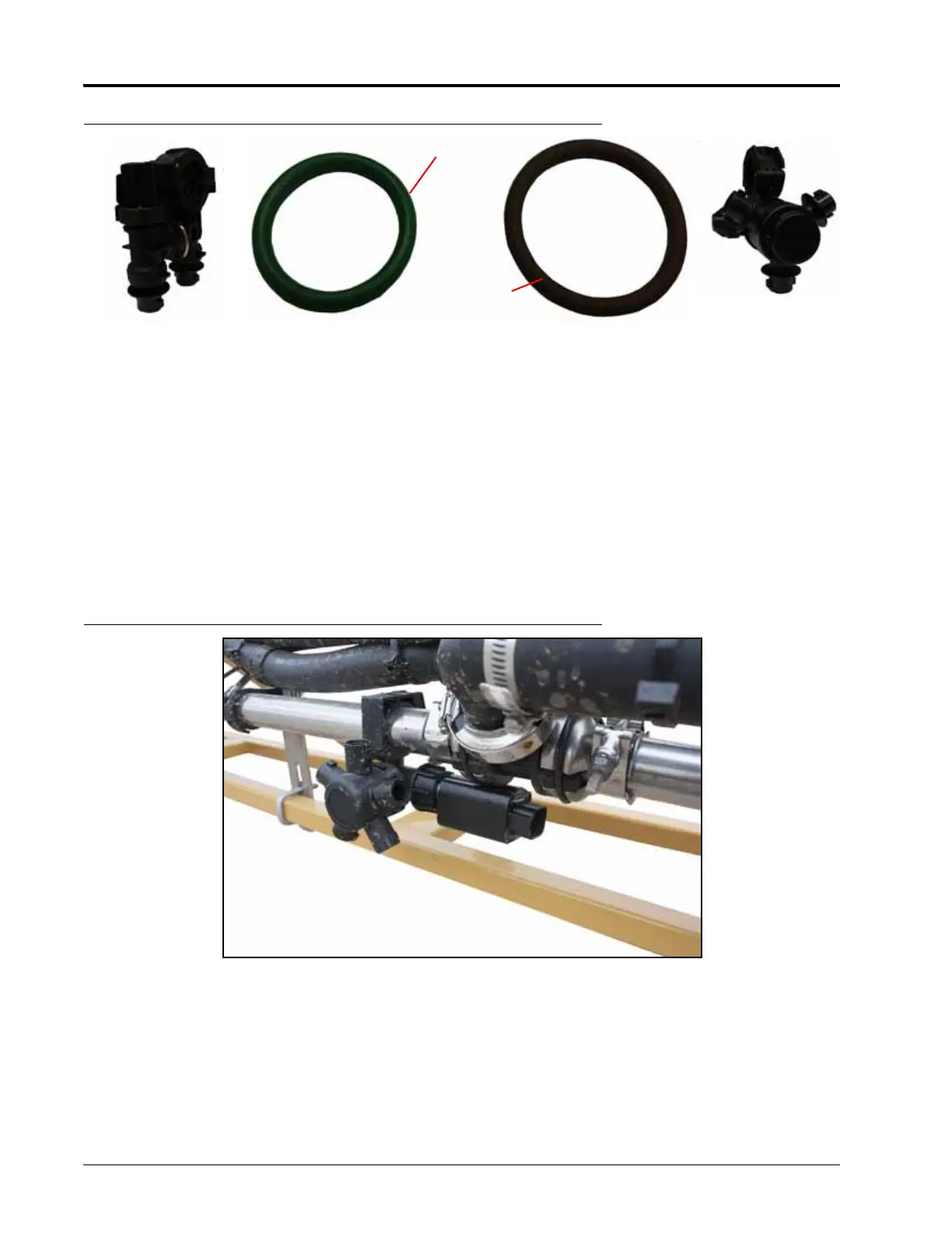
FIGURE 2. Green Coated and Brown/Gray O-Rings
2. Thread the fly nut onto the nozzle body.
3. Orient the nozzle control valve so that the label is easily readable.
4. Hand tighten the swivel nut to secure the nozzle control valve to the nozzle body. Do not over tighten.
NOTE: Frequently check the nozzle control valve fly nuts to ensure they are secure.
VALVE MOUNTING INTERFERENCE AND OBSTRUCTIONS
In some locations on the spray boom, boom equipment or hardware may interfere with mounting the Hawkeye
nozzle control valves. In these locations, there are a few options to get around the interferences:
1. Rotate the nozzle control valve so the round, low profile side of the NCV is towards the interference.
FIGURE 3. Modified Nozzle Control Valve Installation
2. Loosen the brackets and slide them down, out of the way of the NCV. Verify the brackets still adequately
support the components as intended. Do not remove the brackets completely.
3. If the first two options do not solve the interference, swap the AGCO nozzle body for a triple nozzle body
(provided in the kit) with the threaded connection for the Hawkeye valve facing away from the interference.
Green Coated
Brown/Gray
Straight Nozzle Body
Turret Nozzle Body