4
P/N 016-0171-588 Rev. D 17
NOZZLE CONTROL VALVE INSTALLATION
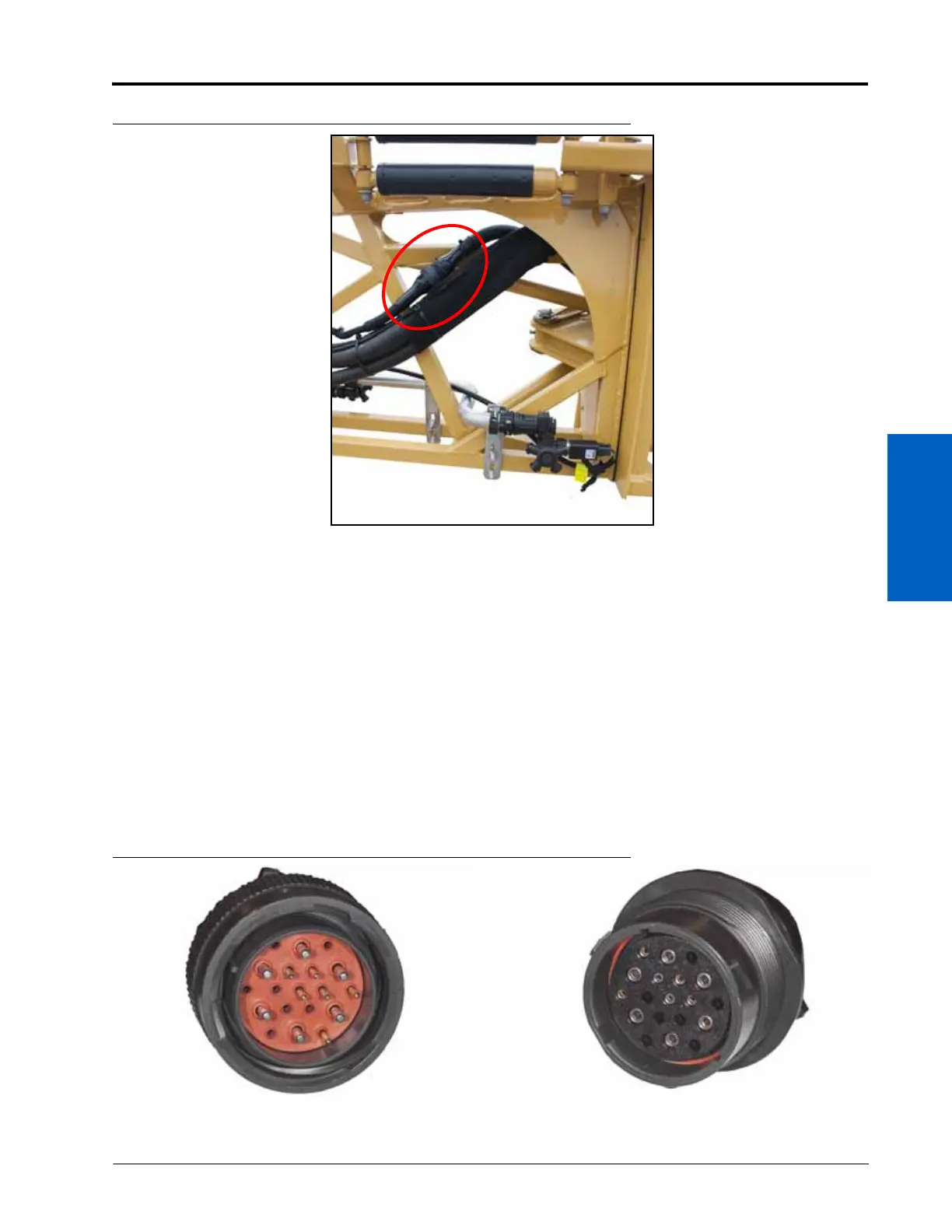
FIGURE 7. Primary and Secondary Boom Cable Connection at Mid-Boom Fold Point
6. Repeat step 1 through step 5 to route and connect the secondary boom cable on the opposite boom.
NOTE: Route and connect the primary and secondary cables before securing the cable with the supplied zip
ties.
PRIMARY BOOM CABLE ROUTING AND CONNECTIONS
NOTE: Review the Best Practices and Recommendations section on page 15 before routing or securing the
boom cables on the implement. Do not connect or secure the cable until instructed to do so in the
procedure.
1. Locate the large, round connectors on the primary boom cables (refer to the Kit Contents section on page 7).
Route the primary cables so the connector with female pins is located at the mid-boom fold point of the left or
right boom and will connect to the secondary boom cable.
FIGURE 8. Primary Cable Ends
Female Receptacle
To Secondary Boom Cable/Mid-Boom
Fold Point
Male Connector
To Center Rack/Chassis Connector
 Loading...