CHAPTER 5
22 AGCO RoGator RG900/1100/1300 Hawkeye™ Installation Manual
3. Reuse the hardware from the boom/speed node or single product node to mount the ISO Boom/Speed Sense
ECU to the side of the mounting plate facing toward the front of the machine (refer to Figure 4 on page 21).
NOTE: It may be necessary to insert the supplied 1/4” bolts and washers required for mounting the Product
Controller II ECU prior to securing the ISO Boom/Speed Sense ECU.
4. Use the supplied 1/4” bolts, hex nuts, and flat washers to mount the Product Controller II ECU to the mounting
plate facing toward the rear of the machine.
ECU ELECTRICAL CONNECTIONS
RETROFIT CABLE INSTALLATION (115-0172-085 CABLE REV A - REV C)
Check the label on the 115-7303-085 cable to determine which cable revision you have. If revision D or later skip to
“Retrofit Cable Installation (115-0172-085 Cable Rev d and later and 115-0172-325 Rev B)” on page 24.
1. Locate the large, round receptacle on the Hawkeye retrofit cable (P/N 115-7303-085).
2. Remove the nut and washer from the receptacle.
3. Feed the receptacle through the hole previously drilled through the back of the electrical box (refer to Figure 3
on page 21).
4. Replace the washer and nut onto the connector from the back of the electrical box to secure the receptacle.
5. Route the opposite end of the cable harness to the product controller II ECU.
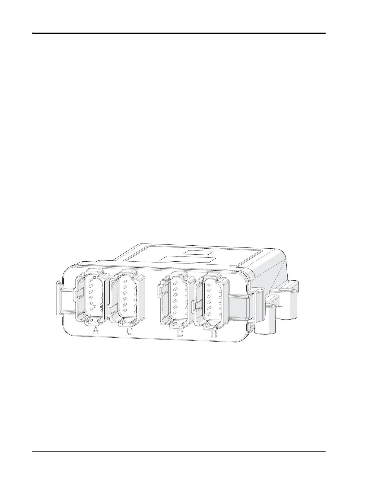
6. Insert the four 12-pin Deutsch plugs (gray, green, brown, and black) into the Product Controller II ECU as shown
inFigure 5 on page 22. Push each connector in until both retaining clips lock into place.
FIGURE 5. Product Controller II ECU Connections
7. Reinstall the node mounting plate into the electrical box and use a socket and socket extension to secure the
plate in place with the existing hardware.
8. Locate the branch on the retrofit cable with the three black rectangular ISOBUS connectors.
9. Route these connectors to the ISOBUS bar along the side of the electrical box closest to the rear of the
machine.