5
P/N 016-0171-588 Rev. D 21
ISOBUS ECU MOUNTING AND CONNECTION
FIGURE 3. Access to Electrical Box for Hawkeye Chassis Cable
MOUNTING PLATE PREPARATION AND ECU INSTALLATION
1. Using the Product Controller II ECU as a template, mark the mounting plate for the new ECU mounting post
pattern. It may be possible to use some existing holes in the plate.
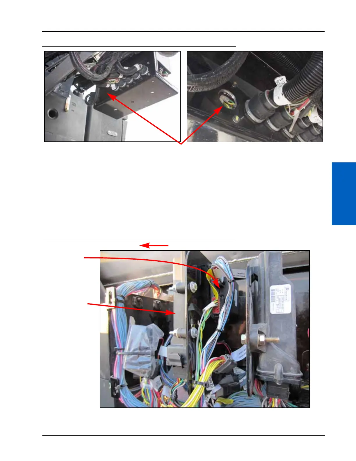
NOTE: Mount the Product Controller II ECU to the side of the plate facing toward the rear of the machine
with the cable connectors pointing toward the bottom of the electrical box. Position the ECU parallel
with the top edge of the mounting plate. Keep in mind the electrical box cover when positioning and
marking the plate for mounting the Product Controller II ECU.
FIGURE 4. Example of Final Product Controller II ECU Mounting
2. Use a 5/16” drill bit to make any holes in the mounting plate.
Product
Controller II
ECU
ISOBUS
Boom/Speed
ECU
Rear of Machine
 Loading...