CHAPTER 6
32 AGCO RoGator RG900/1100/1300 Hawkeye™ Installation Manual
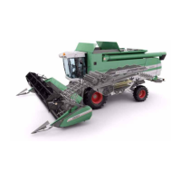
FIGURE 5. Battery Disconnect Switch Location
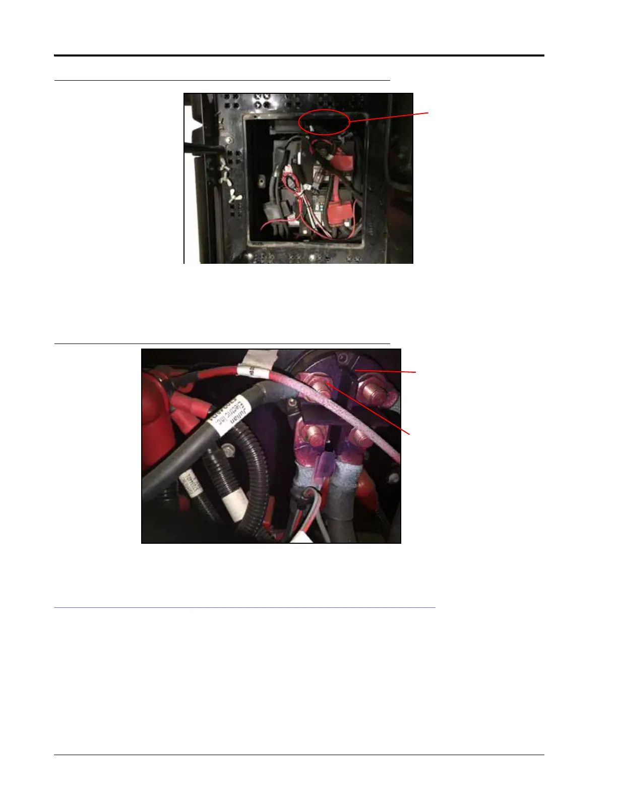
8. Remove the nut from the top-left terminal on the battery disconnect switch.
9. Connect the negative lead from the chassis cable to the negative bolt on the battery disconnect switch and
reinstall the nut.
FIGURE 6. Battery Disconnect Switch
10. When installation is complete, re-connect the battery disconnect switch before operating the equipment.
SYSTEM DIAGRAM
Diagrams start on the next page.
Battery Disconnect
Switch
Battery Disconnect
Switch
Nut