4
P/N 016-0171-588 Rev. D 15
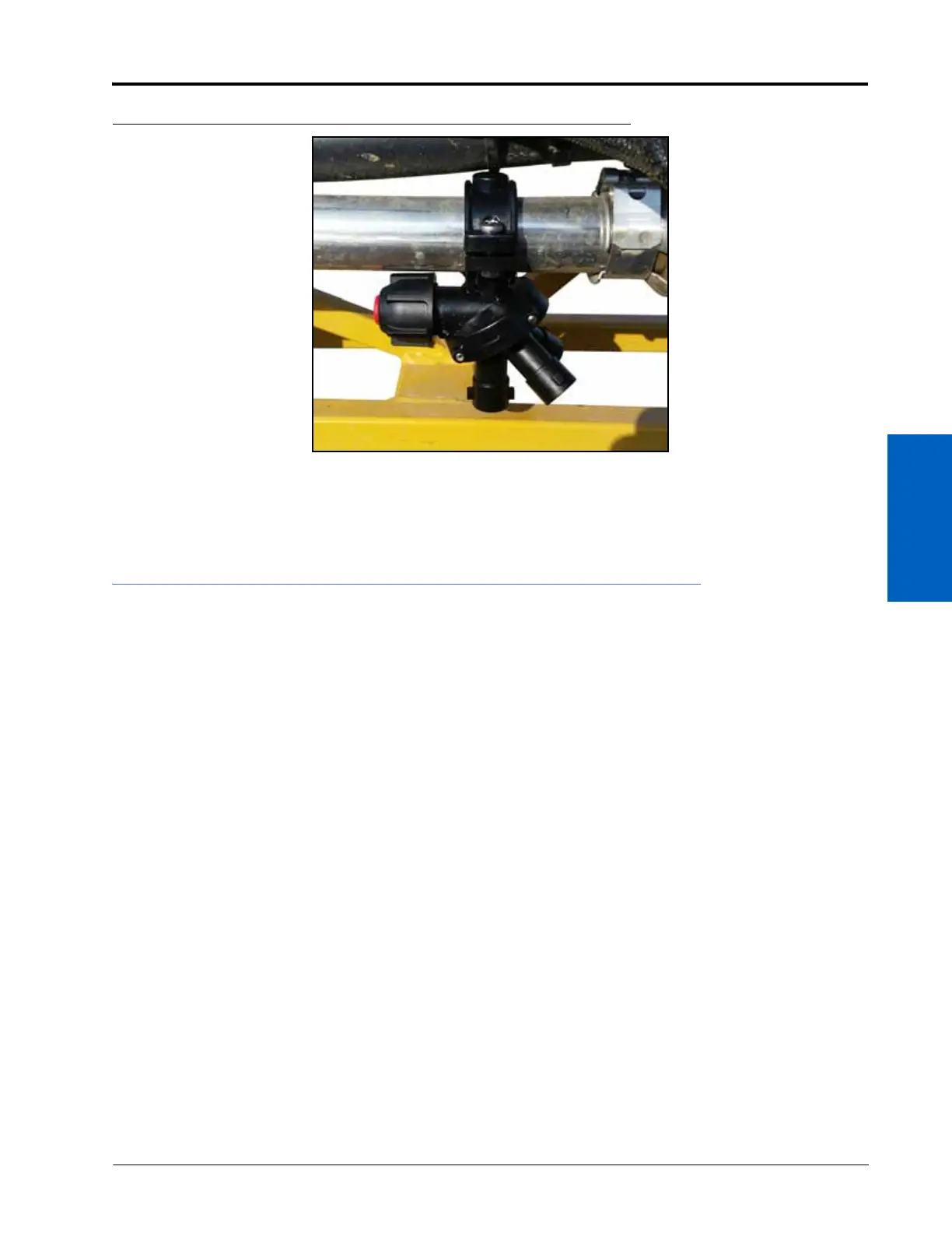
NOZZLE CONTROL VALVE INSTALLATION
FIGURE 4. Triple Nozzle Body Installed
NOTE: Avoid removing of any existing boom hardware or support brackets where applicable during
installation of the Hawkeye nozzle control valves.
BOOM CABLE ROUTING AND CONNECTION
BEST PRACTICES AND RECOMMENDATIONS
• Route the Hawkeye primary and secondary boom cables along existing cables or plumbing to avoid cable
damage.
• Route cables to avoid pinch points and to avoid stretching the cable during folding and unfolding operations.
Pay special attention to cable routing near folding or break-away points.
• Route cables through existing cable retention devices as appropriate.
• When securing the primary and secondary boom cables on the implement, begin at the outer boom tips.
Adjust the cable position to provide sufficient slack between valve tee branches while working toward the
center of the implement.
• Route the boom cables on the inside of the boom frame when available.
• Secure cables using a zip tie at each nozzle control valve tee branch, and one between each tee branch along
the cable length.
SECONDARY BOOM CABLE ROUTING AND CONNECTIONS
NOTE: Please review the Best Practices and Recommendations section on page 15 before routing or securing
the boom cables on the implement. Do not connect or secure the cable until instructed to do so in
the procedure.
1. Locate the terminator on each of the secondary boom cables (refer to the Kit Contents section on page 7).