CHAPTER 4
16 AGCO RoGator RG900/1100/1300 Hawkeye™ Installation Manual
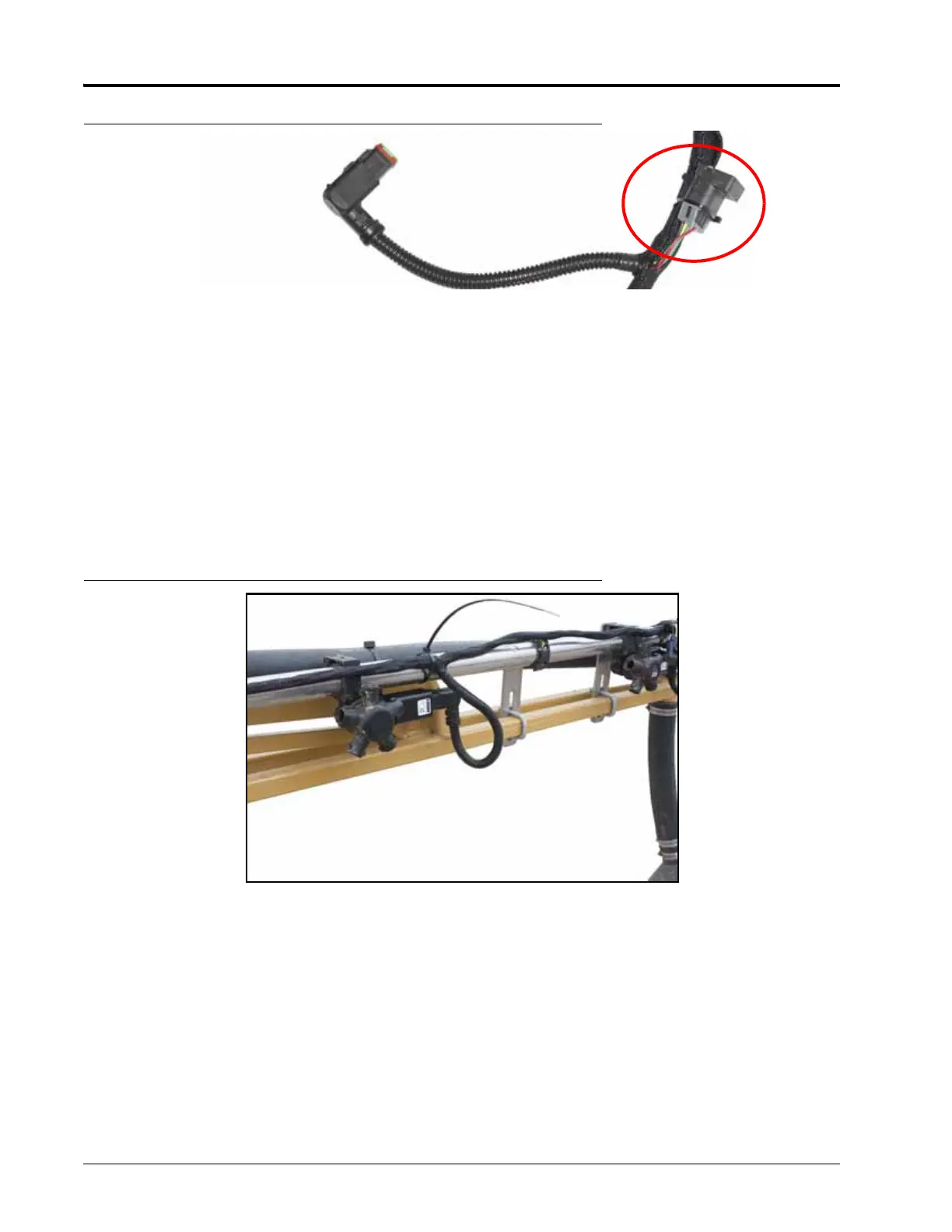
FIGURE 5. Secondary Cable ISOBUS Powell Terminator
NOTE: Verify the terminators are secured to the main cable trunk using a zip tie through the connector
retainer clip. If terminators are not secured, wire breakage could occur.
2. Route the secondary boom cables so they are located at the outer tips of the left and right boom.
3. Starting from the mid-boom fold point, feed the terminator end of the secondary boom cable through the
boom framework along existing cable or plumbing runs and through any existing cable retention devices as
appropriate.
NOTE: If there is interference between the connector and boom components, remove the 90° back shell
from the connector. Refer to Figure 7 on page 17.
4. Starting with the nozzle control valve at the outer end of the boom, begin connecting the valve tee branches to
the nozzle control valves.
FIGURE 6. Securing Valve Branches
5. At each valve branch, adjust the cable as necessary to provide slack between nozzle control valve connections.
The large round connector on the secondary boom cable should reach to the mid-boom fold point after all
nozzle control valves are connected.