CHAPTER
4
P/N 016-0171-588 Rev. D 13
CHAPTER 4
NOZZLE CONTROL VALVE
INSTALLATION
HAWKEYE NOZZLE CONTROL VALVE INSTALLATION
After rinsing the debris out of the plumbing, mount the Hawkeye™ nozzle control valves to the existing nozzle
bodies.
BEST PRACTICES AND RECOMMENDATIONS
• Do not connect battery leads until all cables are installed and connected.
• If a dual channel turret nozzle body is installed on the implement, always mount the Hawkeye nozzle control
valve to the straight nozzle port to avoid excessive pressure drop across the nozzle.
• If there are obstacles that interfere with the Hawkeye valve installation it may be necessary to purchase a
different brand of nozzle body with a threaded port on the opposite side.
GENERAL VALVE INSTALLATION
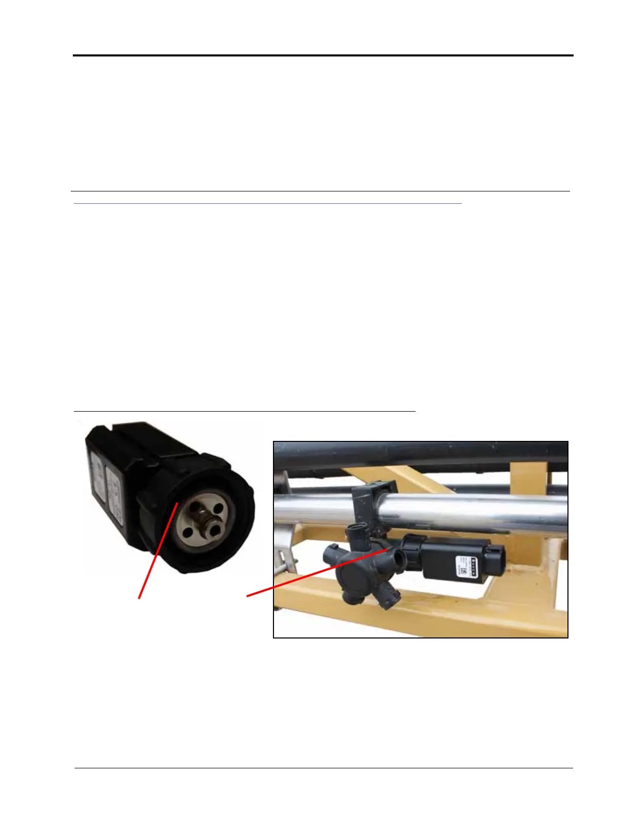
FIGURE 1. Valve Face O-Ring and Nozzle Control Valve
1. Place the supplied o-ring on the inside of the fly nut flush with the valve body face.
NOTE: If using TeeJet QJS (straight) nozzle bodies, use the green coated (size 115) o-ring. For AGCO Hypro
nozzle bodies, use the green coated (size 115) o-ring. For TeeJet QJ (turret) nozzle bodies, use the
brown/gray (size 116) o-rings.
Valve Body Face O-
Ring
Nozzle
Body