Do you have a question about the AGCO RoGator 900 and is the answer not in the manual?
Lists components that must be installed with the Hawkeye nozzle control system.
Instructions for mounting the Hawkeye nozzle control valves to existing nozzle bodies.
Specific instructions for secondary boom cable routing and connections.
Steps for installing the Product Controller II ECU.
Installation steps for the retrofit cable.
Guidelines for routing and connecting chassis cables.
Best practices for chassis cable routing.
| Brand | AGCO |
|---|---|
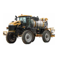
| Model | RoGator 900 |
| Category | Farm Equipment |
| Language | English |