P/N 016-0171-588 Rev. D 27
ISOBUS ECU MOUNTING AND CONNECTION
SECTION VALVE CABLE CONNECTIONS
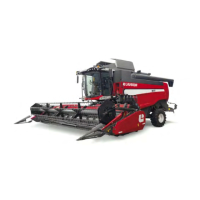
1. Disconnect the two brown “AccuBoom Tee” connections located earlier in the installation process.
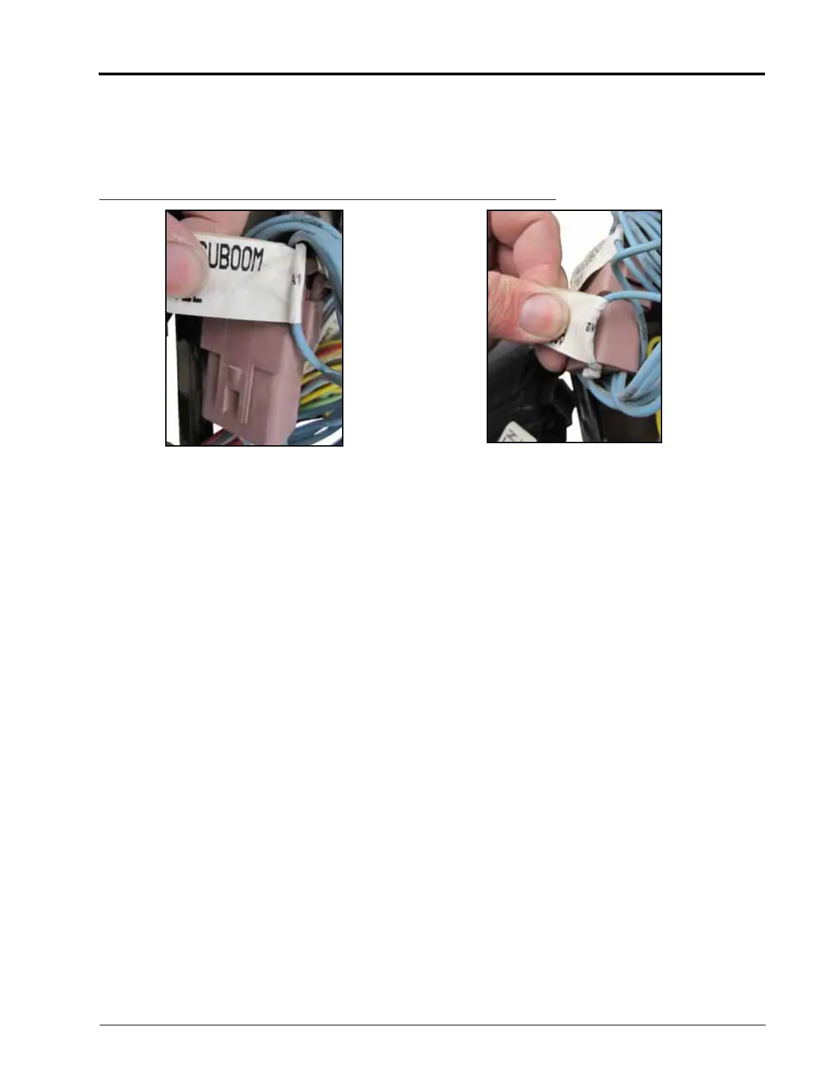
2. Locate the existing plug and receptacle labeled with an ‘A1’ and ‘A2’ or ‘N1’ and ‘N2’ at the base of the label and
connect these two together.
FIGURE 11. A1 and A2 Connectors
3. Locate the existing female “AccuBoom Tee” receptacle labeled ‘E1’ or ‘KB1’ and connect to the brown receptacle
labeled “From Boom Switches” on the supplied Hawkeye Retrofit Cable (P/N 115-7303-084).
4. Locate the existing male “AccuBoom Tee” plug labeled ‘E2’ or ‘KB2’ and connect to the brown receptacle
labeled “boom section valves” on the Hawkeye Logic Power/CAN Retrofit cable (P/N 115-7303-085).
NOTE: The remaining 12-pin plug and receptacle lead to the AccuBoom node which is no longer used with
the Hawkeye system. These connectors will not be used. Connect this plug and receptacle together to
protect the pins from corrosion.
NOTE: After Hawkeye system installation is complete, if the boom switches or valves do not operate
correctly, it is possible the wrong connectors were identified above. Switching connectors should
correct the issue.
5. Tuck cables back into the electrical box and replace the cover.
 Loading...