Chapter 3 Disassembly/Assembly Procedures and Parts List 57
Then remove the pushrod by pulling it out of the front panel from
the rear.
4. Set the 3458A on your workbench with the top facing you.
5. Refer to Figure 22. Do the following:
a. Locate and pull the Front/Rear switch pushrod off the Front/Rear
Terminals switch. You may need to pry the pushrod loose with a
small screwdriver. Then remove the pushrod by pulling it out of
the front panel from the rear.
b. With a small flat bladed screwdriver, pry the top trim loose and
remove from the Front Panel assembly.
6. Set the 3458A on your workbench with the left side facing you.
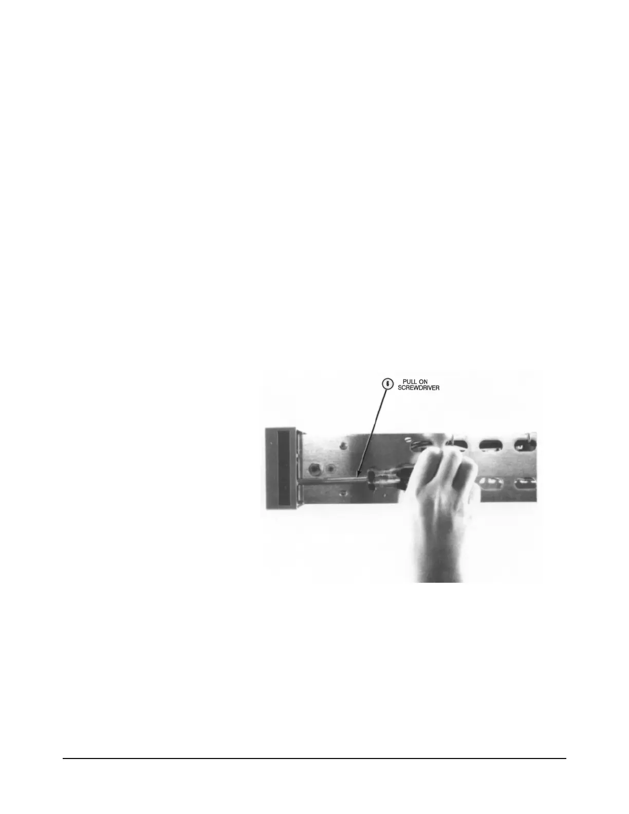
7. Refer to Figure 23. Insert a large screwdriver between the Front Panel
assembly and the chassis, as shown in the figure. With the
screwdriver, carefully pry the left side of the Front Panel assembly
loose. Move the front panel out of the chassis until it unlocks from the
chassis. Do not move it any more, or it may break.
Figure 23. Remove Front Panel Assembly
8. Refer to Figure 22. With a small flat bladed screwdriver, lift up the
Front Panel assembly and unlock it from the chassis. Carefully move
some more of the Front Panel assembly's left side (as seen from the
front of the instrument) until free from the chassis. Then move the rest
of the Front Panel assembly out and away from the instrument as far as
it can go. Note that the assembly can only be moved a short distance,
since the front terminals are still internally connected to the
instrument.

 Loading...


