58 Chapter 3 Disassembly/Assembly Procedures and Parts List
9. Turn the instrument so the front panel faces you.
10. Locate and unscrew (rotate counterclockwise) the current terminal
binding post until it stops. Push in on the terminal and rotate it
clockwise. Then remove the current terminal/fuse assembly.
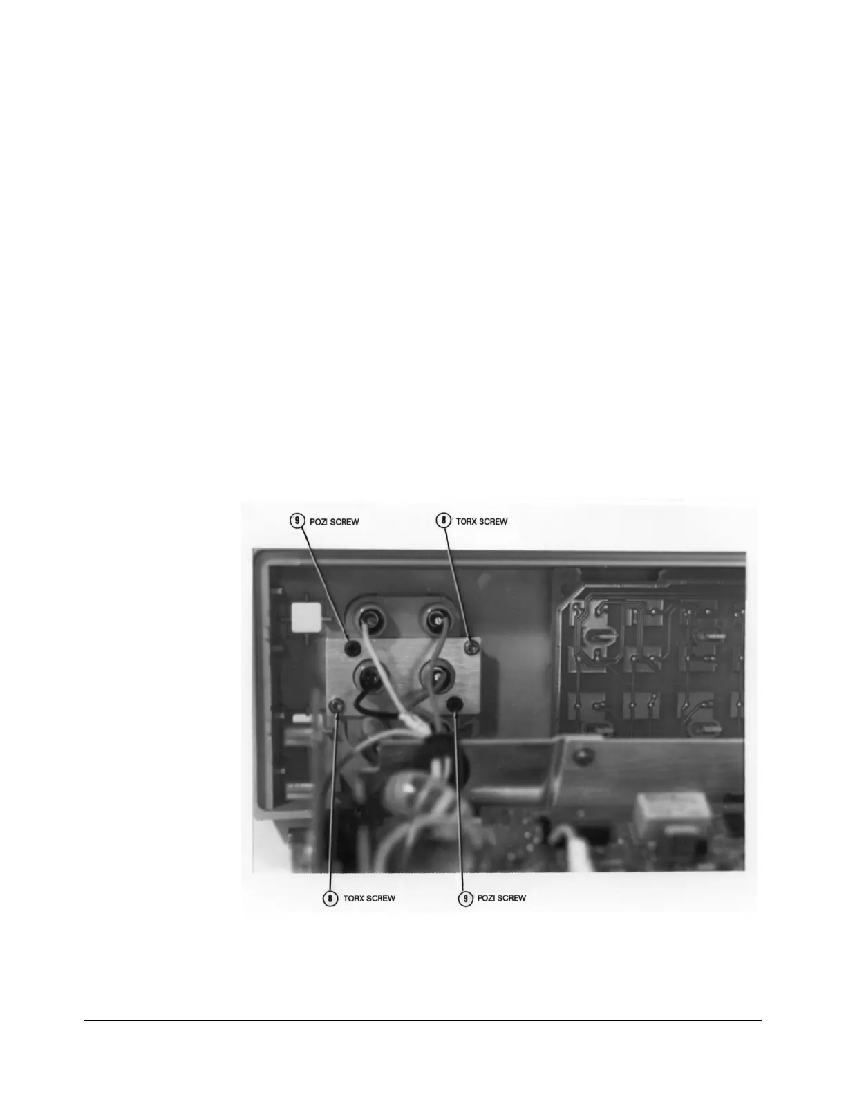
11. Refer to Figure 24. Use the #TX10 Torx driver to remove the two
Torx screws from the front terminals. Then use a #1 Pozidriv
screwdriver to remove the two Pozidriv screws from the front
terminals. This removes the front terminals from the Front Panel
assembly.
12. Completely remove the Front Panel assembly from the instrument.
13. Place the Front Panel assembly face down on a soft anti-static mat.
14. Refer to Figure 25. Use the #TX10 Torx driver to remove the single
Torx screw from the Display assembly.
15. Push the Display board toward the left (with input terminals at your
right side) as far as it can go. Then pull its bottom up and lift it out
from the Front Panel assembly.
Figure 24. Remove/Install Screws on Front Terminals

 Loading...


