Chapter 3 Disassembly/Assembly Procedures and Parts List 59
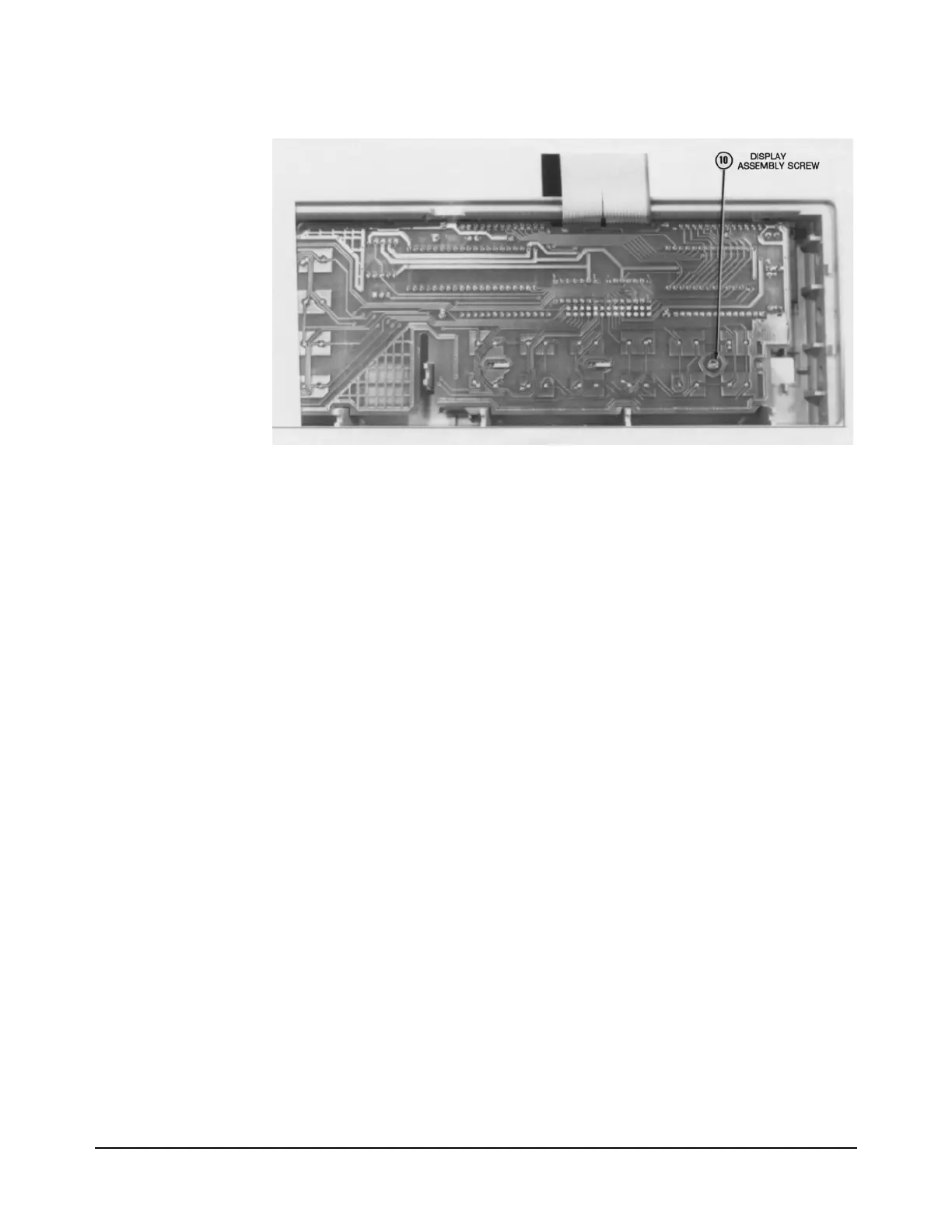
Figure 25. Remove/Install Display Screw
Installation Procedure 1. Align the slots in the Display assembly with the hook tabs on the Front
Panel assembly. Be sure the board is as close to the left side of the
Front Panel assembly as possible. Then push the board down until it
locks in place.
2. Push the board as far as possible toward the right side of the Front
Panel assembly.
3. Refer to Figure 25. Use the #TX10 Torx driver to install the screw on
the Display assembly.
4. Set the 3458A on your workbench with the right side facing you.
5. Carefully place the front terminals into the appropriate holes in the
front panel.
6. Refer to Figure 24. Use the #TX10 Torx driver to install the two Torx
screws on the front terminals. Then use a #1 Pozidriv screwdriver to
install the two Pozidriv screws on the front terminals.
7. Set the 3458A on your workbench with the front facing you.
8. Place the Front Panel assembly in front of the chassis. Place the cable
from the display below the power transformer.
9. Align the Front Panel assembly with the instrument chassis. Be sure
the extension on the center portion of the instrument chassis is aligned
with the slot in the display board.
10. Place the right side of the Front Panel assembly over the standoffs on

 Loading...


