Note
Connect
the sp
ectrum analyzer's
10 MHz
frequency
reference
output
to
the
4395A
EXT
REF
Input
on
the rear
panel as
shown
in Figure
2-6.
With this
conguration, b
oth the
spectrum
analyzer and
the 4395A
are
phase
lo
c
k
ed
to
the
same
reference
frequency
to
eliminate
frequency
oset
errors.
2. Initialize
the
sp
ectrum
analyzer,
and
p
erform
the
FREQ
ZER
O
calibration
in
accordance
with
the
sp
ectrum
analyzer
man
ual.
3.
On the
spectrum
analyzer, set
the con
trols
as
follo
ws:
Con
trols
Settings
Reference
Lev
el
+10
dBm
4.
Press
4
Meas
5
,
N
N
N
N
N
N
N
NN
NN
NN
N
N
N
N
N
N
N
N
N
N
N
N
N
N
N
N
N
N
N
NN
NN
NN
N
N
N
ANALYZER
TYPE
,
N
N
N
N
N
N
N
NN
NN
NN
N
N
N
N
N
N
N
N
N
N
N
N
N
N
N
N
N
N
N
NN
NN
NN
N
N
N
N
N
N
N
N
N
N
N
N
NETWORK
ANALYZER
,
4
Preset
5
to initialize
the 4395A
.Then
set
the con
trols as
follows:
Con
trol
Settings
Key
Strok
es
F
requency
Span:
0
Hz
4
Span
5
,
N
N
NN
NN
N
N
N
N
N
N
N
N
N
N
N
N
N
N
N
N
N
N
N
N
N
NN
ZERO
SPAN
Source
P
o
w
er:
+10
dBm
4
Source
5
,
N
N
N
NN
N
N
N
N
N
N
N
N
N
N
N
N
POWER
,
4
1
5
,
4
0
5
,
4
x1
5
5.
|Harmonics
T
est|
a.
On
the
4395A
,
press
4
Center
5
,
4
1
5
,
4
0
5
,
4
k/m
5
to
set
the
cen
ter
frequency
to
the
rst
cen
ter
frequency
listed in
the rst
column
of
T
able
2-6
.
T
able
2-6
lists
test
frequencies.
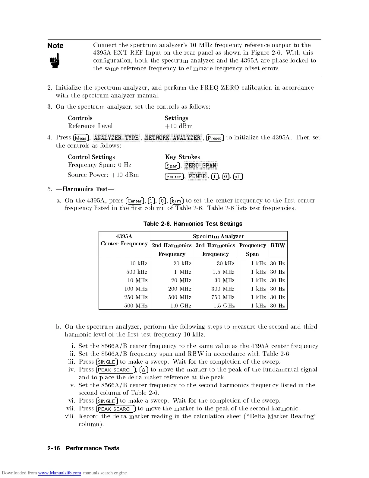
T
able
2-6.
Harmonics
T
est
Settings
4395A
Cen
ter
F
requency
Sp
ectrum
Analyzer
2nd
Harmonics
3rd
Harmonics
F
requency
RBW
F
requency
F
requency
Span
10
kHz
20
kHz
30
kHz
1
kHz
30
Hz
500
kHz
1
MHz
1.5
MHz
1
kHz
30
Hz
10
MHz
20
MHz
30
MHz
1
kHz
30
Hz
100
MHz
200
MHz
300
MHz
1
kHz
30
Hz
250
MHz
500
MHz
750
MHz
1
kHz
30
Hz
500
MHz
1.0
GHz
1.5
GHz
1
kHz
30
Hz
b.
On
the
sp
ectrum
analyzer,
p
erform
the
following
steps
to
measure
the
second
and
third
harmonic lev
el of the rst test
frequency 10 kHz.
i. Set the 8566A/B cen
ter frequency to the same v
alue as the 4395A cen
ter frequency
.
ii. Set the 8566A/B frequency span and RBW in accordance with T
able 2-6
.
iii. Press
4
SINGLE
5
to
makeasw
eep. W
ait for the completion of the sw
eep.
iv. Press
4
PEAK SEARCH
5
,
4
1
5
to mo
ve the mark
er to the p eak of the fundamen
tal
signal
and to place the delta mak
er reference at the peak.
v. Set the 8566A/B cen
ter frequency to the second harmonics frequency listed in the
second column of Table 2-6.
vi. Press
4
SINGLE
5
to makeasweep. Wait for the completion of the sweep.
vii. Press
4
PEAK SEARCH
5
to move the marker to the p eak of the second harmonic.
viii. Record the delta marker reading in the calculation sheet (\Delta Marker Reading"
column).
2-16 Performance Tests
 Loading...


