described below and refer to Figure 4-19 and the
troubleshooting procedures of Figure 4-20.
a. Connect oscilloscope Channel A at 2 volts/div to
STATUS SELECT (U327, pin 11).
b. Trigger on Channel A, negative slope. Set time base to
10µS/div.
c. The STATUS SELECT line should go low for about
30µS. During this interval, each of the six TTL
compatible status output lines from U327 can be
checked against the information given in the table on
Figure 4-19 by connecting Channel B of the oscilloscope
to the IC pin in question.
d. The five status input lines to U327 can also be checked
with the scope. The input lines should be relatively
clean dc waveforms (unless there are load transients
occurring). The input lines are not TTL signals. Check
Table 4-16 for the voltage values that correspond to a
particular input line being High or Low.
e. Follow the procedures outline in Figure 4-20.
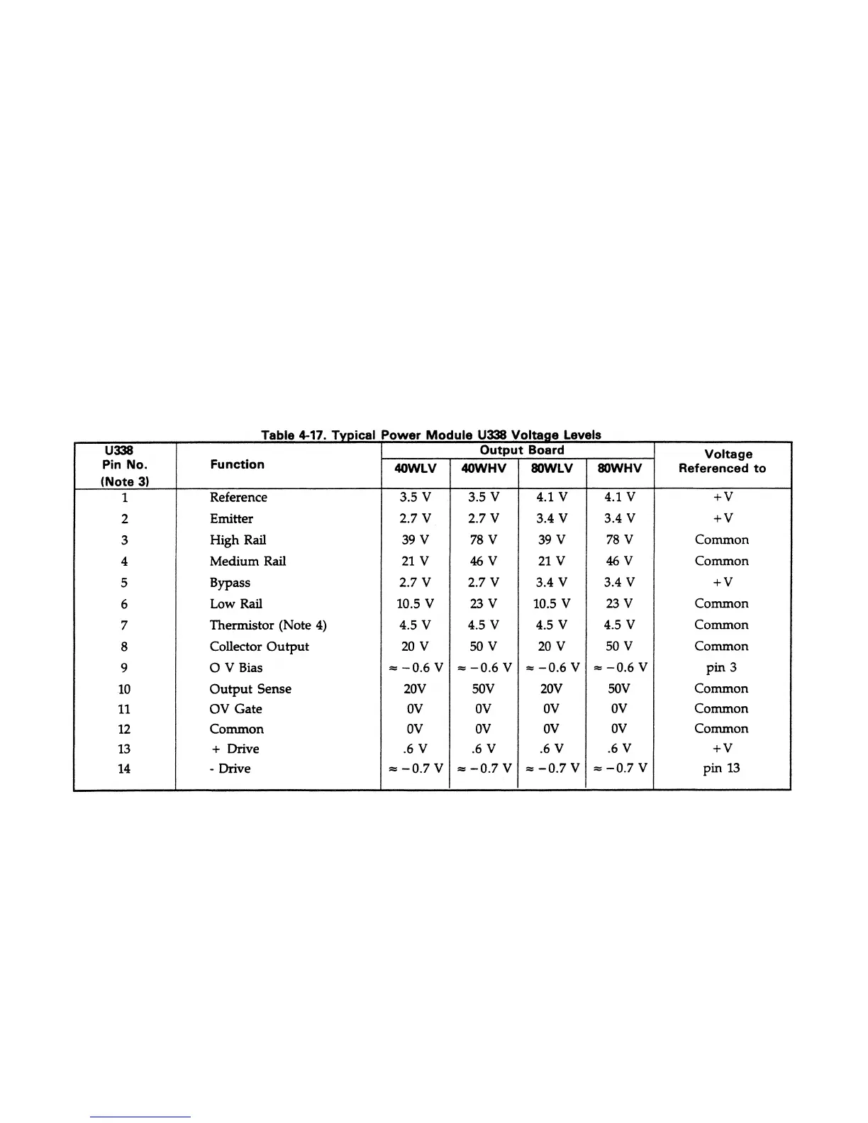
4-33 Power Module Signals
Table 4-17 gives the function and typical signal levels at
each pin for a properly operating power module(s): U338 on
40W output boards, U338 and U339 on 80W output boards.
As indicated in the table, the voltage levels were measured
with the output voltage set to the maximum programmable
value, with no load connected to the output, and at nominal
line voltage.
4-34 Miscellaneous Trouble Symptoms and
Remedies
Table 4-18 lists various trouble symptoms along with
suggested remedies. Most of the trouble symptoms are
concerned with an output not meeting a particular
specification. Verification tests for all specifications are
given in Section III of this manual.
Notes:
1. Conditions:
a. Output voltage set to maximum. programmable value (20 V or 50 V).
b. No load on output
c. Nominal line voltage
2. Voltages are referenced to + V or Common or another power module pin as indicated in the table.
3. Power Module U339 is connected in parallel with U338 on 80WLV and 80WHV boards and has the same voltage levels and
connections as U338 (see Figure 6-3 sheet 3) except that the OV GATE input (pin 11) to U339 is tied to common. U338 and
U339 are matched pairs and should be replaced as such. Agilent Part No. 5080-2111 contains a matched pair of U338/U339
power modules.
4. The Thermistor output (pin 1) level of 4.5 V was measured at a temperature of 25°C. Voltage decreases with a rise in
temperature. OVERTEMP occurs at approximately 2.5 V.
4-54
______________
______________